Intel SE7500WV2 Product Guide
Intel SE7500WV2 - Server Chassis - SR2300 Manual
 |
UPC - 735858157049
View all Intel SE7500WV2 manuals
Add to My Manuals
Save this manual to your list of manuals |
Intel SE7500WV2 manual content summary:
- Intel SE7500WV2 | Product Guide - Page 1
Intel® SR2300 Chassis Subassembly Product Guide A Guide for Technically Qualified Assemblers of Intel® Identified Subassemblies/Products Order Number: A86100-002 - Intel SE7500WV2 | Product Guide - Page 2
any other application in which the failure of the Intel product could create a situation where personal injury or death may occur. Intel may make changes to specifications and product descriptions at any time, without notice. Intel, Intel Xeon and Pentium are trademarks or registered trademarks of - Intel SE7500WV2 | Product Guide - Page 3
SCSI Hard Drives 13 Flex Bay...14 500 Watt Redundant Power Supply 14 480 Watt Power Supply ...14 System Cooling ...14 Chassis Security...15 Locking and Unlocking the Front Bezel 15 2 Assembling the System Before You Begin ...17 Supplies Needed ...17 Installation/Assembly Safety Instructions - Intel SE7500WV2 | Product Guide - Page 4
/FDD Module 49 Replacing a PCI Add-in Card 50 Replacing a 480 Watt Power Supply Module 53 Replacing a Power Supply Cage 54 Installing a Redundant Fan 56 Replacing the Fan Module 58 Replacing a Backplane Board 59 Replacing a Front Panel Board 60 Replacing a Server Board 61 A Regulatory and - Intel SE7500WV2 | Product Guide - Page 5
the Cover 21 7. Removing the Processor Air Duct 22 8. Removing a Riser Card 23 9. Removing the Fan module 24 10. Mounting the Server Board SE7500WV2 26 11. Installing the Processor Air Dam 27 12. Cable Routing...28 13. Connecting the Main Power Cable 29 14. Installing the Fan module 30 15 - Intel SE7500WV2 | Product Guide - Page 6
module 58 41. Replacing a Backplane Board 59 42. Removing the Front Panel Board 60 43. Removing the Server Board 61 Tables 1. Control Button Functions 12 2. LED Indicator Status 12 3. Power Usage Worksheet 1 71 4. Power Usage Worksheet 2 72 vi Intel SR2300 Chassis Subassembly Product Guide - Intel SE7500WV2 | Product Guide - Page 7
) • Intel Server Board SE7500WV2 (SCSI) • Minimum of one Intel® Xeon™ processor • Registered ECC DDR RAM memory DIMMs • SCSI hard disk drives (HDD) • Slimline DVD/CD-ROM drive/floppy disk drive module (optional) • PCI add-in cards • Hard drive carriers (over the four supplied) • 500 W power supply - Intel SE7500WV2 | Product Guide - Page 8
System Components D C AB EFG H I J K L O M N OM14080 A. Power supply J. Intrusion switch B. PCI card bracket (full-length) K. Control panel C. Riser card assembly (full-length) D. PCI card bracket (low-profile) E. Server board (accessory to system) F. PCI add-in card (accessory to system - Intel SE7500WV2 | Product Guide - Page 9
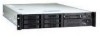
and gently pull it towards you until it unsnaps from the chassis. AB C D E F A. Chassis handles (2) B. Drive bay (1-inch) C. HDD activity/fault Indicator D. Flex bay (optional DVD/CD-ROM drive/FDD module shown installed) E. Front panel indicator lights F. Tape drive bay (tape drive not included - Intel SE7500WV2 | Product Guide - Page 10
OM14082 K. PS/2† mouse/keyboard connector L. RJ45 NIC 1 connector M. SCSI channel A connector (If available) N. Video connector O. USB connector 1 *480 Watt redundant power supply shown. Your power supply may be different. Figure 3. Chassis Back 10 Intel SR2300 Chassis Subassembly Product Guide - Intel SE7500WV2 | Product Guide - Page 11
. AB C D EF G L KJ Figure 4. Controls and Indicators A. NIC 2 activity LED B. Power button C. Power/sleep LED D. Fixed disk drive status LED E. System status LED F. ID LED G. ID button H. Reset button I. USB Connector J. NMI button K. Video Connector H I OM14083 Chassis Description 11 - Intel SE7500WV2 | Product Guide - Page 12
the BIOS clears it. If the system is not powered down normally, it is possible that the Power LED will be blinking at the same time that the System Status LED is off due to a failure or configuration change that prevents the BIOS from running. 12 Intel SR2300 Chassis Subassembly Product Guide - Intel SE7500WV2 | Product Guide - Page 13
Figure 5. Peripherals OM14084 Hot Swappable SCSI Hard Drives The chassis ships with four drive carriers for mounting SCSI hard drives in the hard drive page 38. The SCSI hard drives are hot swappable. When a drive fails, the SCSI backplane detects the failure, reports it, and powers down the failed - Intel SE7500WV2 | Product Guide - Page 14
fan may be added to provide cooling redundancy for system components. The system fans are mounted in a fan module located in the middle of the chassis to pull cooling air through the chassis. The power supply contains a single fan for cooling. 14 Intel SR2300 Chassis Subassembly Product Guide - Intel SE7500WV2 | Product Guide - Page 15
bezel, which provides a key lock. The chassis also includes a preinstalled intrusion switch for the top access cover that can be monitored by server management software. When the cover is opened, the switch, located on the front panel board, transmits a signal to the Baseboard Management Controller - Intel SE7500WV2 | Product Guide - Page 16
16 Intel SR2300 Chassis Subassembly Product Guide - Intel SE7500WV2 | Product Guide - Page 17
for the system. The following procedures help guide you through this assembly process and create supplies available: • Anti-static wrist strap (recommended) • SR2300 accessory kit (included) • SE7500WV2 SCSI server board kit • Processors and memory you purchased separately to add to the server board - Intel SE7500WV2 | Product Guide - Page 18
of: • Sharp pins on connectors • Sharp pins on printed circuit assemblies • Rough edges and sharp corners on the chassis • Hot components (like processors, heat sinks, and power supply modules) • Damage to wires that could cause a short circuit 18 Intel SR2300 Chassis Subassembly Product Guide - Intel SE7500WV2 | Product Guide - Page 19
in your region. • The connector that plugs into the AC receptacle on the power supply must be an IEC 320, sheet C13, type female connector. • In Europe, the server. 2. Turn off the server by pressing the power button on the front of the chassis. Then unplug all AC power cords from the chassis or - Intel SE7500WV2 | Product Guide - Page 20
, personal injury or equipment damage can result. WARNING Do not open the power supply. Hazardous voltage, current and energy levels are present inside the power supply. Refer servicing of the power supply to qualified technical service personnel. 20 Intel SR2300 Chassis Subassembly Product Guide - Intel SE7500WV2 | Product Guide - Page 21
thumb, slide the top cover back using the heel of your right hand on the blue pad. ✏ NOTE A non-skid surface or a stop behind the chassis may be needed if attempting to remove the top cover on a flat surface. 2. Set the cover aside and away from the immediate work area. A Figure - Intel SE7500WV2 | Product Guide - Page 22
Remove the Processor Air Duct Lift the processor air duct out of the chassis. OM14583 Figure 7. Removing the Processor Air Duct 22 Intel SR2300 Chassis Subassembly Product Guide - Intel SE7500WV2 | Product Guide - Page 23
Remove the Riser Cards 1. Insert your finger in the plastic loop. On riser card (A), also grasp the opposite end at (C). 2. Pull straight up and remove the riser card from the chassis. 3. Discard the protective blocks. A B Figure 8. Removing a Riser Card OM14087 Assembling the System 23 - Intel SE7500WV2 | Product Guide - Page 24
4. While pushing on the tab, lift up on the module to clear the retention stub. 5. Slide the module towards the power supply until it comes free. 6. Lift the fan module out of the chassis. 3 2 1 C B A Figure 9. Removing the Fan module OM14088 24 Intel SR2300 Chassis Subassembly Product Guide - Intel SE7500WV2 | Product Guide - Page 25
Install the Server Board CAUTION Do not install any server board support bumpers in the SR2300 chassis. System components must be installed in the order presented below. If installed in a different order, component damage may occur. 1. Ensure that the insulator sheet is - Intel SE7500WV2 | Product Guide - Page 26
C A D OM14090 Figure 10. Mounting the Server Board SE7500WV2 26 Intel SR2300 Chassis Subassembly Product Guide - Intel SE7500WV2 | Product Guide - Page 27
6. Install processors and memory, following the directions on the Intel Server Board SE7500WV2 Quick Start User Guide. 7. If you only install one processor, you must install the processor air dam. a. Attach processor retention piece (B) to the server board (C) using the provided screws (A). b. Put - Intel SE7500WV2 | Product Guide - Page 28
board fan connectors (2) H. To server board auxiliary signal connector from power supply I. To server board auxiliary power connector from power supply J. Serial cable from server board to knockout on back of chassis Figure 12. Cable Routing 28 Intel SR2300 Chassis Subassembly Product Guide - Intel SE7500WV2 | Product Guide - Page 29
power cable is routed from the power supply to the backplane board and is connected to the white 6-pin connector. 2. Connect the main server board power cable to the white 24-pin connector on the server board chassis floor. 3. Align the holes in the fan module with the raised tabs on the chassis and - Intel SE7500WV2 | Product Guide - Page 30
2 3 A C 1 B Figure 14. Installing the Fan module 5. Connect the fan power cables to the server board (Figure 15). OM14577 A OM14586 Figure 15. Connecting Fans to the Server Board 30 Intel SR2300 Chassis Subassembly Product Guide - Intel SE7500WV2 | Product Guide - Page 31
flex circuit cable from the cable bag in the accessory kit. Connect the end marked "P1-Motherboard" to the floppy/front panel/IDE connector on the server board. Route the cable to the backplane board and connect the other cable end to the matching connector on the backplane. B C A OM14584 Figure - Intel SE7500WV2 | Product Guide - Page 32
1. Connect the auxiliary power cable to the 8-pin auxiliary power connector on the server board (A). 2. Connect the signal cable to the 5-pin signal connector on the server board (B). B A OM14585 Figure 19. Connecting the Auxiliary Power Cables 32 Intel SR2300 Chassis Subassembly Product Guide - Intel SE7500WV2 | Product Guide - Page 33
Finish Cable Routing 1. Connect the USB cable to the USB connector on the front panel. Route the cable along the top of the fan module and connect it to the server board. Make sure the cable does not lay on top of the corner of the backplane or it will get damaged when you - Intel SE7500WV2 | Product Guide - Page 34
in the bottom of the baffle. A B OM14582 Figure 21. Installing the Power Supply Air Baffle 4. Connect the SCSI cable to the SCSI connector on the server board. Route the cable between the memory connectors and the full height PCI riser, through the clips on the side of the processor duct, through - Intel SE7500WV2 | Product Guide - Page 35
equipped with a standard full-height PCI mounting bracket). PCI add-in cards must be installed on a riser card while the riser card is removed from the chassis. If you do not have PCI cards to install, proceed to page 37, "Installing the Riser Cards on the Server Board". ✏ NOTES If you install a NIC - Intel SE7500WV2 | Product Guide - Page 36
D A B C OM14097 Figure 23. Installing a Full-Length PCI Card in a Riser Card 36 Intel SR2300 Chassis Subassembly Product Guide - Intel SE7500WV2 | Product Guide - Page 37
the Server Board 1. Align the riser card connector with the server board slot. 2. Firmly press the riser card straight down until it is fully seated in the server board slot. Make sure the tabs on the rear retention bracket are aligned with the holes in the chassis. 3. Install the other riser card - Intel SE7500WV2 | Product Guide - Page 38
the four screws (B) from the slide track (C). 4. Store the air baffle for future reinstallation in the event you must operate your server without a drive in one of the bays. A B C OM14099 Figure 25. Removing an Air Baffle from a Drive Carrier 38 Intel SR2300 Chassis Subassembly Product Guide - Intel SE7500WV2 | Product Guide - Page 39
its wrapper and place it on an anti-static surface. 6. Set any jumpers and/or switches on the drive according to the drive manufacturer's instructions. 7. With the drive circuit-side-down (Figure 26, A), position the connector end (E) so that it is facing the back of the carrier (B). 8. Align the - Intel SE7500WV2 | Product Guide - Page 40
server does not come with a DVD drive, CD-ROM drive or floppy disk drive. As an accessory, Intel offers slim-line DVD drive/FDD and CD-ROM drive/FDD modules that you may purchase and install in the flex bay. 1. Remove the filler panel (Figure 27, A) and plug (B) from the front of the chassis - Intel SE7500WV2 | Product Guide - Page 41
NOTE If you are placing the server in a rack, wait to install the power cord until after the server is in the rack. 1. Attach the strain relief strap to the chassis (A). 2. Plug the power cord into the power supply but not into the power source. 3. Insert the power cord into the plastic loop (B) of - Intel SE7500WV2 | Product Guide - Page 42
Install the Bezel Place the bezel between the chassis handles and push it toward the front of the chassis until it snaps into place. Figure 29. Installing the Bezel OM14108 42 Intel SR2300 Chassis Subassembly Product Guide - Intel SE7500WV2 | Product Guide - Page 43
support to prevent it from falling over when one or more servers are extended in front of it on slide assemblies. The equipment rack must be installed according to the manufacturer's instructions grounding conductor with the rack installation. If server power cords are plugged into AC outlets that - Intel SE7500WV2 | Product Guide - Page 44
in temperature can cause a variety of problems in your server. Ventilation: The equipment rack must provide sufficient airflow to the front of the server to maintain proper cooling. It must into a large error calculating air conditioning capacity. 44 Intel SR2300 Chassis Subassembly Product Guide - Intel SE7500WV2 | Product Guide - Page 45
server after it has been set up. All references to left, right, front and rear are based on the reader facing the front of the chassis. Tools and Supplies 2. Turn off the system by pressing the power button on the front of the system. Then unplug the AC power cord from the system or wall outlet. 3. - Intel SE7500WV2 | Product Guide - Page 46
warning is provided on the server board configuration label, which is provided with the Intel server board boxed product. There is insufficient space on the server board to place this label. Therefore, the label must be placed permanently on the inside of the chassis, as close to the battery - Intel SE7500WV2 | Product Guide - Page 47
work inside the system, observe the safety guidelines on page 45. 2. Remove the bezel from the front of the chassis. 3. Pull the retention lever (A) toward you until the tab end (B) of the lever is free of the housing wrapper and place it on an anti-static surface. Working Inside Your Server 47 - Intel SE7500WV2 | Product Guide - Page 48
7. Set any jumpers and/or switches on the drive according to the drive manufacturer's instructions. A B C D OM14110 Figure 31. Removing a Hard Drive from a Carrier 8. Install the air baffle in any bays where you are not reinstalling a carrier/drive. 48 Intel SR2300 Chassis Subassembly Product Guide - Intel SE7500WV2 | Product Guide - Page 49
, you must first take the server out of service, turn off all peripheral devices connected to the system, turn off the system by pressing the power button, and unplug the AC power cord from the system or wall outlet. 1. Remove the bezel from the front of the chassis. 2. Rotate the handle bar (A) up - Intel SE7500WV2 | Product Guide - Page 50
is latched. 9. Insert the riser card connector in the server board slot while aligning the tabs on the rear retention bracket with the holes in the chassis. 10. Firmly press the riser card straight down until it is seated in the server board slot. 50 Intel SR2300 Chassis Subassembly Product Guide - Intel SE7500WV2 | Product Guide - Page 51
A B OM14112 Figure 33. Removing the Low-Profile PCI Riser Card Working Inside Your Server 51 - Intel SE7500WV2 | Product Guide - Page 52
A B OM14113 Figure 34. Removing the Full-Length PCI Riser Card 52 Intel SR2300 Chassis Subassembly Product Guide - Intel SE7500WV2 | Product Guide - Page 53
do not have the second, redundant power supply module, you must take the server out of service before replacing the single module. 1. Squeeze toward you (C). As you pull the module out, support the module with your free hand. 3. Insert a new power supply module in the bay. 4. Grip the module handle - Intel SE7500WV2 | Product Guide - Page 54
power supply modules (redundant power supply only). 4. Remove the chassis cover. 5. Remove the full-height PCI riser card. 6. Remove the fan module. 7. Disconnect and remove all data cabling necessary to gain access to the power cables. 8. Disconnect the main power connector from the server board - Intel SE7500WV2 | Product Guide - Page 55
the chassis and the one screw at the fan end of the power supply. 15. Plug the main power connector into the server board. 16. Connect all other power cables to their devices. 17. Install the fan module and connect the fan power cables to the server board. 18. Install the full-height PCI riser card - Intel SE7500WV2 | Product Guide - Page 56
towards the power supply until it comes free. 9. Lift the fan module out of the chassis. 3 2 1 C B A Figure 37. Removing the Fan module 10. Remove the fan blank from the fan module. A OM14088 B Figure 38. Removing the Fan Blank OM14587 56 Intel SR2300 Chassis Subassembly Product Guide - Intel SE7500WV2 | Product Guide - Page 57
cables into the server board system fan connectors. 16. Make sure the USB cable is routed along the top of the fan module. 17. Connect the flex circuit cable to the backplane. 18. Install the flex circuit cable retention clip. 19. Install the full-height PCI riser card. 20. Replace the chassis cover - Intel SE7500WV2 | Product Guide - Page 58
the server board system fan connectors. 13. Make sure the USB cable is routed along the top of the fan module. 14. Connect the flex circuit cable to the backplane. 15. Install the flex circuit cable retention clip. 16. Install the full-height PCI riser card. 17. Replace the chassis cover. 58 Intel - Intel SE7500WV2 | Product Guide - Page 59
the full-height PCI riser card assembly. 5. Remove the fan module. 6. Unplug all cables connected to the backplane board. 7. Remove the thumbscrew (Figure 41, A) along the top of the board and lift it out of the chassis. 8. Lower the replacement backplane board into the chassis, inserting the lower - Intel SE7500WV2 | Product Guide - Page 60
11. Install the fan module. 12. Install the full-height PCI riser card. 13. Install all hard drives and peripherals in their bays. 14. Install the chassis cover. Replacing a Front Panel Board 1. Before removing the cover to work inside the system, observe the safety guidelines on page 45. 2. Remove - Intel SE7500WV2 | Product Guide - Page 61
guidelines on page 45. 2. Disconnect all cables from the rear I/O of the chassis. 3. Remove the cover from the chassis. 4. Remove the PCI riser cards. 5. Remove the fan module. 6. Unplug all cables connected to the server board. 7. Remove any processors and DIMMs that you wish to use with the new - Intel SE7500WV2 | Product Guide - Page 62
and cooling problems. 15. Cable the new server board to the other system components. 16. Install the fan module. 17. Install the PCI riser cards. 18. Replace the chassis cover. 19. Connect any cables removed from the rear I/O of the chassis. 62 Intel SR2300 Chassis Subassembly Product Guide - Intel SE7500WV2 | Product Guide - Page 63
instructions in this guide to ensure and maintain compliance with existing product certifications and approvals. Use only the described, regulated components specified in this guide Regulatory Compliance The SR2300 chassis subassembly, when correctly integrated per this guide, complies with the - Intel SE7500WV2 | Product Guide - Page 64
server chassis will be marked with the following regulatory markings. cULus Listing Marks German GS Mark CE Mark FCC Marking (Class A) Canada EMC Marking (Class A) Japan VCCI Marking (Class A) BSMI Certification Number Taiwan BSMI Marking (Class A) Russia GOST R Marking Korea RRL MIC Mark 64 Intel - Intel SE7500WV2 | Product Guide - Page 65
including interference that may cause undesired operation. Intel Corporation 5200 N.E. Elam Young Parkway Hillsboro, and used in accordance with the instructions, may cause harmful interference to radio Only peripherals (computer input/output devices, terminals, printers, etc.) that comply with FCC - Intel SE7500WV2 | Product Guide - Page 66
. If this is used near a radio or television receiver in a domestic environment, it may cause radio interference. Install and use the equipment according to the instruction manual. 66 Intel SR2300 Chassis Subassembly Product Guide - Intel SE7500WV2 | Product Guide - Page 67
's web address please contact your local Intel representative. • SR2300 chassis (base chassis is provided with power supply and fans)UL listed. • Server boardyou must use an Intel Server Board - UL Recognized. • Add-in boardsmust have a printed wiring board flammability rating of minimum UL94V - Intel SE7500WV2 | Product Guide - Page 68
68 Intel SR2300 Chassis Subassembly Product Guide - Intel SE7500WV2 | Product Guide - Page 69
information about your system. You will need some of this information when you run the SSU. Item Chassis Manufacturer Name and Model Number Serial Number Date Installed Server Board Processor Speed and Cache Video Display Video Controller Keyboard Mouse 3.5-inch Drive CD-ROM Drive Hard Disk - Intel SE7500WV2 | Product Guide - Page 70
Equipment Log (continued) Item Hard Disk Drive 7 Manufacturer Name and Model Number DAT Tape Drive Serial Number Date Installed 70 Intel SR2300 Chassis Subassembly Product Guide - Intel SE7500WV2 | Product Guide - Page 71
column, then go to the next worksheet. Table 3. Power Usage Worksheet 1 Current (maximum) at voltage level: Device +5 Vsb +3.3 V +5 V Boards, processors, and memory (get totals from your board manual) SCSI backplane and front panel 0.40 3.5-inch drive 0.30 CD-ROM drive 0.60 3.5-inch - Intel SE7500WV2 | Product Guide - Page 72
Watts for each voltage level ________ W ________ W ________ W ________ W ________ W ________ W CAUTION Do not overload: As an overall current usage limitation on the power supply, do not exceed a combined power output of 250W for all DC outputs. 72 Intel SR2300 Chassis Subassembly Product Guide - Intel SE7500WV2 | Product Guide - Page 73
C Safety Warnings WARNING: English (US) AVERTISSEMENT: Français WARNUNG: Deutsch AVVERTENZA: Italiano ADVERTENCIAS: Español 73 - Intel SE7500WV2 | Product Guide - Page 74
supply in this product. Refer servicing only to qualified personnel. Do not attempt to modify or use the supplied AC power cord if it is not the exact type required. A product with more than one power supply will have a separate AC power cord for each supply. The power with the chassis covers removed - Intel SE7500WV2 | Product Guide - Page 75
the AC power cord(s) to the system. A microprocessor and heat sink may be hot if the system has been running. Also, there may be sharp pins and edges on some board and chassis parts. outlet. • Provided with sufficient space to access the power supply cord(s), because they serve as the product's main - Intel SE7500WV2 | Product Guide - Page 76
panneaux du système. Procédez comme suit: 1. Retirez toutes les vis des panneaux et mettez-les dans un endroit sûr. 2. Retirez les panneaux. suite 76 Intel SR2300 Chassis Subassembly Product Guide - Intel SE7500WV2 | Product Guide - Page 77
. Remplacer uniquement avec une batterie du même type ou d'un type équivalent recommandé par le fabricant. Disposez des piles usées selon les instructions du fabricant. Le système a été conçu pour fonctionner dans un cadre de travail normal. L'emplacement choisi doit être: • Propre et dépourvu de - Intel SE7500WV2 | Product Guide - Page 78
SICHERHEITSSCHRITTE durchgeführt haben, können Sie die Abdeckung abnehmen, indem Sie: 1. Entfernen Sie alle Schrauben der Gehäuseabdeckung. 2. Nehmen Sie die Abdeckung ab. Fortsetzung 78 Intel SR2300 Chassis Subassembly Product Guide - Intel SE7500WV2 | Product Guide - Page 79
WARNUNG: Deutsch (Fortsetzung) Zur ordnungsgemäßen Kühlung und Lüftung muß die Gehäuseabdeckung immer wieder vor dem Einschalten installiert werden. Ein Betrieb des Systems ohne angebrachte Abdeckung kann Ihrem System oder Teile darin beschädigen. Um die Abdeckung wieder anzubringen: 1. Vergewissern - Intel SE7500WV2 | Product Guide - Page 80
, togliere le coperture del telaio del sistema come seque: 1. Togliere e mettere in un posto sicuro tutte le viti delle coperture. 2. Togliere le coperture. continua 80 Intel SR2300 Chassis Subassembly Product Guide - Intel SE7500WV2 | Product Guide - Page 81
AVVERTENZA: Italiano (continua) Per il giusto flusso dell'aria e raffreddamento del sistema, rimettere sempre le coperture del telaio prima di riaccendere il sistema. Operare il sistema senza le coperture al loro proprio posto potrebbe danneggiare i componenti del sistema. Per rimettere le coperture - Intel SE7500WV2 | Product Guide - Page 82
alterna que tenga el producto. Nótese que el interruptor activado/desactivado en el panel frontal no desconecta la corriente alterna del sistema. Para desconectarla, deberá desenchufar todos tornillos de las tapas. 2. Extraiga las tapas. continúa 82 Intel SR2300 Chassis Subassembly Product Guide - Intel SE7500WV2 | Product Guide - Page 83
ADVERTENCIAS: Español (continúa) Para obtener un enfriamiento y un flujo de aire adecuados, reinstale siempre las tapas del chasis antes de poner en marcha el sistema. Si pone en funcionamiento el sistema sin las tapas bien colocadas puede dañar los componentes del sistema. Para instalar las tapas: - Intel SE7500WV2 | Product Guide - Page 84
84 Intel SR2300 Chassis Subassembly Product Guide - Intel SE7500WV2 | Product Guide - Page 85
errata are available upon request. This Limited Warranty does not cover damages due to external causes, including accident, problems with electrical power, usage not in accordance with product instructions, misuse, neglect, alteration, repair, improper installation, or improper testing. 85 - Intel SE7500WV2 | Product Guide - Page 86
the above limitations or exclusions may not apply to you. This limited warranty gives you specific legal rights, and you may also have other rights that vary from jurisdiction to jurisdiction Warranty, the English language version shall control. 86 Intel SR2300 Chassis Subassembly Product Guide - Intel SE7500WV2 | Product Guide - Page 87
instructions: http://support.intel.com/support/motherboards/draform.htm In Europe and in AsiaContact your original authorized distributor for warranty service 803-65-7249 800-6310003 IDD call +63(2)6368416 (0006517) 830-3634 Manual toll free. From India, you need an IDD-equipped phone. IDD call - Intel SE7500WV2 | Product Guide - Page 88
Returning a Defective Product Before returning any product, call your authorized dealer/distribution authority. 88 Intel SR2300 Chassis Subassembly Product Guide
-
 1
1 -
 2
2 -
 3
3 -
 4
4 -
 5
5 -
 6
6 -
 7
7 -
8
-
9
-
10
-
11
-
12
-
13
-
14
-
15
-
16
-
17
-
18
-
19
-
20
-
21
-
22
-
23
-
24
-
25
-
26
-
27
-
28
-
29
-
30
-
31
-
32
-
33
-
34
-
35
-
36
-
37
-
38
-
39
-
40
-
41
-
42
-
43
-
44
-
45
-
46
-
47
-
48
-
49
-
50
-
51
-
52
-
53
-
54
-
55
-
56
-
57
-
58
-
59
-
60
-
61
-
62
-
63
-
64
-
65
-
66
-
67
-
68
-
69
-
70
-
71
-
72
-
73
-
74
-
75
-
76
-
77
-
78
-
79
-
80
-
81
-
82
-
83
-
84
-
85
-
86
-
87
-
88
 |
 |

Intel
®
SR2300 Chassis Subassembly
Product Guide
A Guide for Technically Qualified Assemblers of Intel
®
Identified Subassemblies/Products
Order Number:
A86100-002