Intel SE7520AF2 User Guide - Page 29
Hot plug systems only, PCI Hot-plug LEDs at Rear of Chassis
 |
View all Intel SE7520AF2 manuals
Add to My Manuals
Save this manual to your list of manuals |
Page 29 highlights
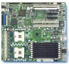
Hardware Installations and Upgrades 4. Hot plug systems only: Use the hot-plug power and attention LEDs at the back of your system or next to the PCI slots inside of the server chassis to ensure it is safe to remove the card. The power LED next to a slot for which a card is to be added or removed must be OFF. If the power LED is green or blinking, do not attempt to add or remove a card in that slot. See the labels on the PCI duct for additional LED information and for LED placement inside of the chassis. A B C D EF TP00859 A PCI Slot 5 (PCI-X* 64-bit/133 MHz) D PCI Slot 1 (PCI-X* 64-bit/133 MHz) B PCI Slot 4 (PCI Express* x8) E Power LED (one for on each PCI slot) C PCI Slot 3 (PCI Express* x4) F Activity LED (one for each hot-plug PCI slot) Figure 14. PCI Hot-plug LEDs at Rear of Chassis 5. If removing or inserting a full-length card from or into the Intel® Server Chassis SC5300, remove the PCI add-in card retainer at the front of the chassis. See letter A in Figure 15. See your server chassis documentation for additional instructions. 6. Pull back on the blue or green rocker switch that holds the PCI bracket shield to the rear of the chassis to remove the shield. See letter B in Figure 15. In a standard system, the rocker switch is blue. In a hot plug system, the switch is green for any PCI slots that can be hot plugged (slots 1, 3, 4, and 5) and it is blue for slots that are not hot pluggable under any circumstances. 7. Hot-plug systems only: when performing a hot removal, place the hot plug curtains on each side of the card to be removed to prevent accidental contact with adjoining "live" cards. 8. If removing a card from the system, pull up on the card to remove it. 9. Insert the PCI card into the PCI slot on the server board. See letter C in Figure 15. In a hot-plug system, stand the hot-plug curtains on each side of the card to be installed and insert the card between them to prevent accidental contact with adjoining "live" cards. Press firmly on the top edge of the riser card until it is fully seated. 18 Intel® Server Board SE7520AF2 User Guide
-
 1
1 -
2
-
3
-
4
-
5
-
6
-
7
-
8
-
9
-
10
-
11
-
12
-
13
-
14
-
15
-
16
-
17
-
18
-
19
-
20
-
21
-
22
-
23
-
 24
24 -
 25
25 -
 26
26 -
 27
27 -
 28
28 -
 29
29 -
 30
30 -
 31
31 -
 32
32 -
 33
33 -
 34
34 -
35
-
36
-
37
-
38
-
39
-
40
-
41
-
42
-
43
-
44
-
45
-
46
-
47
-
48
-
49
-
50
-
51
-
52
-
53
-
54
-
55
-
56
-
57
-
58
 |
 |
