Intel SE7520JR2 User Guide - Page 18
Connector and Header Locations, Server Board Connector and Component Locations
 |
UPC - 735858167376
View all Intel SE7520JR2 manuals
Add to My Manuals
Save this manual to your list of manuals |
Page 18 highlights
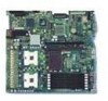
Server Board Features Connector and Header Locations A B C DEF G EE DD CC BB AA Z H Y X I W V U TS Q O M K J R PN L A Serial Port A L Processor 2 fan header TP00757 W SATA port 2 B SCSI Channel B M +12V processor power X Power supply signal cable C 8-pin OEM connector N Fan board connector Y USB header (DH-10) D Battery O Floppy connector Z USB header (1 x 10) E Full-height riser slot P System fan 3-pin header AA IPMB connector F Low-profile riser slot Q Secondary IDE channel BB IDE power connector G Back panel I/O ports R Control panel 100-pin connector CC SCSI channel A H DIMM sockets S 24-pin SSI power connector DD ICMB connector I Processor 1 fan header T 50-pin control panel connector EE 120-pin connector for optional Intel® Management Module J Processor socket 1 U 34-pin SSI control panel connector K Processor socket 2 V SATA port 1 Figure 2. Server Board Connector and Component Locations 18
-
 1
1 -
2
-
3
-
4
-
5
-
6
-
7
-
8
-
9
-
10
-
11
-
12
-
 13
13 -
 14
14 -
 15
15 -
 16
16 -
 17
17 -
 18
18 -
 19
19 -
 20
20 -
 21
21 -
 22
22 -
 23
23 -
24
-
25
-
26
-
27
-
28
-
29
-
30
-
31
-
32
-
33
-
34
-
35
-
36
-
37
-
38
-
39
-
40
-
41
-
42
-
43
-
44
-
45
-
46
-
47
-
48
-
49
-
50
-
51
-
52
-
53
-
54
-
55
-
56
-
57
-
58
-
59
-
60
-
61
-
62
-
63
 |
 |
