Intel SE7520JR2 User Guide - Page 20
Back Panel Connectors, Table 3., NIC LEDs - no video
 |
UPC - 735858167376
View all Intel SE7520JR2 manuals
Add to My Manuals
Save this manual to your list of manuals |
Page 20 highlights
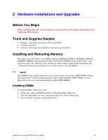
Server Board Features Back Panel Connectors A B C D E F GH I TP00762 A PS/2 Mouse F Video B PS/2 Keyboard G USB port 1 C Serial Port B H USB port 2 D NIC port 1 (1 Gb) I SCSI channel B E NIC port 2 (1 Gb) Figure 4. Back Panel Connectors The NIC LEDs at the right and left of each NIC provide the following information. Table 3. NIC LEDs LED Color LED State Off Left LED Solid Amber Blinking Amber Off Right LED Solid Amber Solid Green Description No network connection Network connection in place Transmit/receive activity 10 Mbps connection (if left LED is on or blinking) 100 Mbps connection 1000 Mbps connection 20
-
 1
1 -
2
-
3
-
4
-
5
-
6
-
7
-
8
-
9
-
10
-
11
-
12
-
13
-
14
-
 15
15 -
 16
16 -
 17
17 -
 18
18 -
 19
19 -
 20
20 -
 21
21 -
 22
22 -
 23
23 -
 24
24 -
 25
25 -
26
-
27
-
28
-
29
-
30
-
31
-
32
-
33
-
34
-
35
-
36
-
37
-
38
-
39
-
40
-
41
-
42
-
43
-
44
-
45
-
46
-
47
-
48
-
49
-
50
-
51
-
52
-
53
-
54
-
55
-
56
-
57
-
58
-
59
-
60
-
61
-
62
-
63
 |
 |

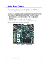
Server Board Features
Back Panel Connectors
TP00762
A
F
C
D
E
G
H
B
I
A PS/2 Mouse
F
Video
B PS/2 Keyboard
G
USB port 1
C Serial Port B
H
USB port 2
D
NIC port 1 (1 Gb)
I
SCSI channel B
E
NIC port 2 (1 Gb)
Figure 4.
Back Panel Connectors
The NIC LEDs at the right and left of each NIC provide the following information.
Table 3.
NIC LEDs
LED Color
LED State
Description
Off
No network connection
Solid Amber
Network connection in place
Left LED
Blinking Amber
Transmit/receive activity
Off
10 Mbps connection (if left LED is on or blinking)
Solid Amber
100 Mbps connection
Right LED
Solid Green
1000 Mbps connection
20