Intel SE7520JR2 User Guide - Page 19
Configuration Jumpers, Configuration Jumper Location, Table 2.
 |
UPC - 735858167376
View all Intel SE7520JR2 manuals
Add to My Manuals
Save this manual to your list of manuals |
Page 19 highlights
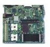
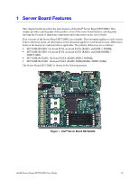
Configuration Jumpers Server Board Features 1-2: Default setting for each jumper set 2 3 A1-A2: Password Clear Protect A A2-A3: Password Clear Erase B B1-B2: Recovery Boot Disable (Normal Boot) B2-B3: Recovery Boot Enable C C1-C2: CMOS Clear by BMC C2-C3: CMOS Clear Force Erase TP00759 Figure 3. Configuration Jumper Location Table 2. Configuration Jumper Jumper Name Pins What happens at system reset... Password Clear 1-2 These pins should be jumpered for normal system operation. (line "A" in figure 2-3 If these pins are jumpered, administrator and user passwords will be cleared on the above) next reset. These pins should not be jumpered for normal operation. Recovery Boot 1-2 These pins should be jumpered for normal system operation. (line "B" in figure 2-3 If these pins are jumpered, the system will attempt to recover the BIOS by loading the above) BIOS code into the flash device from a floppy disk. This jumper is typically used when the BIOS has become corrupted. These pins should not be jumpered for normal operation. CMOS Clear (line 1-2 "C" in figure 2-3 above) These pins should be jumpered for normal system operation. If these pins are jumpered, the CMOS settings will be cleared on the next reset. These pins should not be jumpered for normal operation. Intel® Server Board SE7520JR2 User Guide 19
-
 1
1 -
2
-
3
-
4
-
5
-
6
-
7
-
8
-
9
-
10
-
11
-
12
-
13
-
 14
14 -
 15
15 -
 16
16 -
 17
17 -
 18
18 -
 19
19 -
 20
20 -
 21
21 -
 22
22 -
 23
23 -
 24
24 -
25
-
26
-
27
-
28
-
29
-
30
-
31
-
32
-
33
-
34
-
35
-
36
-
37
-
38
-
39
-
40
-
41
-
42
-
43
-
44
-
45
-
46
-
47
-
48
-
49
-
50
-
51
-
52
-
53
-
54
-
55
-
56
-
57
-
58
-
59
-
60
-
61
-
62
-
63
 |
 |
