Intel SE7520JR2 User Guide - Page 38
Clearing the CMOS, CMOS Recovery Jumper
 |
UPC - 735858167376
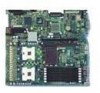
View all Intel SE7520JR2 manuals
Add to My Manuals
Save this manual to your list of manuals |
Page 38 highlights
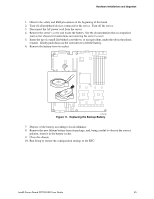
Server Utilities 4. Reconnect the AC power, power up the system. 5. Power down the system and disconnect the AC power. 6. Return the Password Clear jumper to the Password Clear Protect position, covering pins 1 and 2. 7. Close the server chassis. 8. Reconnect the AC power and power up the server. Clearing the CMOS If you are not able to access the BIOS setup screens, the CMOS Clear jumper will need to be used to reset the configuration RAM. The CMOS Clear jumper is shown on the line labeled "C" in the figure below. 1. Power down the system and disconnect the AC power. 2. Open the server. 3. Move the jumper from the normal operation position, CMOS Clear by BMC, at pins 1 and 2 to the CMOS Clear Force Erase position, covering pins 2 and 3 as indicated in the following diagram. 23 A B C TP01241 Figure 13. CMOS Recovery Jumper 4. Reconnect the AC power, power up the system. 5. When the system begins beeping, power it down and disconnect the AC power. 6. Return the CMOS Clear jumper to the CMOS Clear by BMC location, covering pins 1 and 2. 7. Close the server chassis. 8. Reconnect the AC power and power up the system. 38
-
 1
1 -
2
-
3
-
4
-
5
-
6
-
7
-
8
-
9
-
10
-
11
-
12
-
13
-
14
-
15
-
16
-
17
-
18
-
19
-
20
-
21
-
22
-
23
-
24
-
25
-
26
-
27
-
28
-
29
-
30
-
31
-
32
-
 33
33 -
 34
34 -
 35
35 -
 36
36 -
 37
37 -
 38
38 -
 39
39 -
 40
40 -
 41
41 -
 42
42 -
 43
43 -
44
-
45
-
46
-
47
-
48
-
49
-
50
-
51
-
52
-
53
-
54
-
55
-
56
-
57
-
58
-
59
-
60
-
61
-
62
-
63
 |
 |
