Intel SR1560SFHS Service Guide - Page 38
Bezels
 |
UPC - 735858197595
View all Intel SR1560SFHS manuals
Add to My Manuals
Save this manual to your list of manuals |
Page 38 highlights
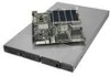
Callout E. F. G. H. I. J. K. L. Feature Hard Disk Drive Activity LED System Status LED System Identification LED System Identification Button Reset Button USB 2.0 Port NMI Button Video Port Function Random blinking green light indicates hard disk drive activity (SAS or SATA). No light indicates no hard disk drive activity. Solid green indicates normal operation. Blinking green indicates degraded performance. Solid amber indicates a critical or non-recoverable condition. Blinking amber indicates a non-critical condition. No light indicates POST is running or the system is off. Solid blue indicates system identification is active. No light indicates system identification is not activated. Turns on/off the system identification LED. Reboots and initializes the system. Allows you to attach a USB component to the front of the chassis. Puts the server in a halt-state for diagnostic purposes. Allows you to attach a video monitor to the front of the chassis. The front and rear video ports cannot be used at the same time. NOTE: Note: the video port option is only available on the hot- swap drive system (product code SR1560SFHS). Figure 11. Standard Control Panel Bezels The optional front bezel provides a snap-on design that allows for maximum airflow through the server system. The bezel fits a system that has the standard control panel installed (with or without a video port). The bezel provides a lock to secure the hard drive and optical drive area. For instructions on installing the front bezel, see "Installing the Front Bezel". The order number for the bezel is: • ADWBEZBLACK: Black bezel for use with the standard control panel. 16 Intel® Server System SR1560SF Service Guide
-
 1
1 -
2
-
3
-
4
-
5
-
6
-
7
-
8
-
9
-
10
-
11
-
12
-
13
-
14
-
15
-
16
-
17
-
18
-
19
-
20
-
21
-
22
-
23
-
24
-
25
-
26
-
27
-
28
-
29
-
30
-
31
-
32
-
 33
33 -
 34
34 -
 35
35 -
 36
36 -
 37
37 -
 38
38 -
 39
39 -
 40
40 -
 41
41 -
 42
42 -
 43
43 -
44
-
45
-
46
-
47
-
48
-
49
-
50
-
51
-
52
-
53
-
54
-
55
-
56
-
57
-
58
-
59
-
60
-
61
-
62
-
63
-
64
-
65
-
66
-
67
-
68
-
69
-
70
-
71
-
72
-
73
-
74
-
75
-
76
-
77
-
78
-
79
-
80
-
81
-
82
-
83
-
84
-
85
-
86
-
87
-
88
-
89
-
90
-
91
-
92
-
93
-
94
-
95
-
96
-
97
-
98
-
99
-
100
-
101
-
102
-
103
-
104
-
105
-
106
-
107
-
108
-
109
-
110
-
111
-
112
-
113
-
114
-
115
-
116
-
117
-
118
-
119
-
120
-
121
-
122
-
123
-
124
-
125
-
126
-
127
-
128
-
129
-
130
-
131
-
132
-
133
-
134
-
135
-
136
-
137
-
138
-
139
-
140
-
141
-
142
-
143
-
144
-
145
-
146
-
147
-
148
-
149
-
150
-
151
-
152
-
153
-
154
-
155
-
156
-
157
-
158
 |
 |
