Intel SR1560SFHS Service Guide - Page 66
Installing the Backplane into the Server System, Installing the Bridge Board
 |
UPC - 735858197595
View all Intel SR1560SFHS manuals
Add to My Manuals
Save this manual to your list of manuals |
Page 66 highlights
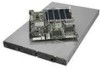
D B A C AF002348 Figure 48. Installing the Backplane into the Server System 4. Connect fan, USB, and front panel cables as necessary to the backplane board. 5. Install the bridge board by opening the retention mechanism (see letter "A") and inserting it into the connector on the server board (see letter "B"). Close the retention mechanism to hold the bridge board in place. B A C A C AF000372 Figure 49. Installing the Bridge Board into the Server System 44 Intel® Server System SR1560SF Service Guide
-
 1
1 -
2
-
3
-
4
-
5
-
6
-
7
-
8
-
9
-
10
-
11
-
12
-
13
-
14
-
15
-
16
-
17
-
18
-
19
-
20
-
21
-
22
-
23
-
24
-
25
-
26
-
27
-
28
-
29
-
30
-
31
-
32
-
33
-
34
-
35
-
36
-
37
-
38
-
39
-
40
-
41
-
42
-
43
-
44
-
45
-
46
-
47
-
48
-
49
-
50
-
51
-
52
-
53
-
54
-
55
-
56
-
57
-
58
-
59
-
60
-
 61
61 -
 62
62 -
 63
63 -
 64
64 -
 65
65 -
 66
66 -
 67
67 -
 68
68 -
 69
69 -
 70
70 -
 71
71 -
72
-
73
-
74
-
75
-
76
-
77
-
78
-
79
-
80
-
81
-
82
-
83
-
84
-
85
-
86
-
87
-
88
-
89
-
90
-
91
-
92
-
93
-
94
-
95
-
96
-
97
-
98
-
99
-
100
-
101
-
102
-
103
-
104
-
105
-
106
-
107
-
108
-
109
-
110
-
111
-
112
-
113
-
114
-
115
-
116
-
117
-
118
-
119
-
120
-
121
-
122
-
123
-
124
-
125
-
126
-
127
-
128
-
129
-
130
-
131
-
132
-
133
-
134
-
135
-
136
-
137
-
138
-
139
-
140
-
141
-
142
-
143
-
144
-
145
-
146
-
147
-
148
-
149
-
150
-
151
-
152
-
153
-
154
-
155
-
156
-
157
-
158
 |
 |

44
Intel
®
Server System SR1560SF Service Guide
Figure 48. Installing the Backplane into the Server System
4.
Connect fan, USB, and front panel cables as necessary to the backplane board.
5.
Install the bridge board by opening the retention mechanism (see letter “A”) and
inserting it into the connector on the server board (see letter “B”). Close the
retention mechanism to hold the bridge board in place.
Figure 49. Installing the Bridge Board into the Server System
AF002348
A
B
C
D
A
B
C
A
C
AF000372