Intel SR1560SFHS Service Guide - Page 47
Installing and Removing Memory - memory configuration
 |
UPC - 735858197595
View all Intel SR1560SFHS manuals
Add to My Manuals
Save this manual to your list of manuals |
Page 47 highlights
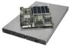
Place the processor air duct over the processor sockets. The front edge of the air duct should contact the fan module. Use caution not to pinch or disengage cables that may be near or under the air duct. AF002363 Figure 20. Installing the Processor Air Duct Installing and Removing Memory The silkscreen on the board for the DIMMs displays DIMM A1, DIMM A2, DIMM A3, DIMM A4, DIMM B1, DIMM B2, DIMM B3, DIMM B4, DIMM C1, DIMM C2, DIMM C3, DIMM C4, DIMM D1, DIMM D2, DIMM D3, and DIMM D4, starting from the center of the board. See "Memory" for a discussion of the memory requirements and options. See "Server System References" for a link to the list of tested DIMMs. Figure 21 shows the supported DIMM configuration that is recommended because it allows both memory branches from the MCH to operate independently and simultaneously. Intel® Server System SR1560SF Service Guide 25
-
 1
1 -
2
-
3
-
4
-
5
-
6
-
7
-
8
-
9
-
10
-
11
-
12
-
13
-
14
-
15
-
16
-
17
-
18
-
19
-
20
-
21
-
22
-
23
-
24
-
25
-
26
-
27
-
28
-
29
-
30
-
31
-
32
-
33
-
34
-
35
-
36
-
37
-
38
-
39
-
40
-
41
-
 42
42 -
 43
43 -
 44
44 -
 45
45 -
 46
46 -
 47
47 -
 48
48 -
 49
49 -
 50
50 -
 51
51 -
 52
52 -
53
-
54
-
55
-
56
-
57
-
58
-
59
-
60
-
61
-
62
-
63
-
64
-
65
-
66
-
67
-
68
-
69
-
70
-
71
-
72
-
73
-
74
-
75
-
76
-
77
-
78
-
79
-
80
-
81
-
82
-
83
-
84
-
85
-
86
-
87
-
88
-
89
-
90
-
91
-
92
-
93
-
94
-
95
-
96
-
97
-
98
-
99
-
100
-
101
-
102
-
103
-
104
-
105
-
106
-
107
-
108
-
109
-
110
-
111
-
112
-
113
-
114
-
115
-
116
-
117
-
118
-
119
-
120
-
121
-
122
-
123
-
124
-
125
-
126
-
127
-
128
-
129
-
130
-
131
-
132
-
133
-
134
-
135
-
136
-
137
-
138
-
139
-
140
-
141
-
142
-
143
-
144
-
145
-
146
-
147
-
148
-
149
-
150
-
151
-
152
-
153
-
154
-
155
-
156
-
157
-
158
 |
 |
