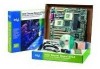
Intel STL2 Quick Start Guide
Intel STL2 - Server Board Motherboard Manual
 |
UPC - 735858140256
View all Intel STL2 manuals
Add to My Manuals
Save this manual to your list of manuals |
Intel STL2 manual content summary:
- Intel STL2 | Quick Start Guide - Page 1
Intel® Server Board STL2 Quick Start Guide Before You Begin 2 Installation Notes Installation Process Quick Reference 4 Common Problems 5 Server Board Components 6 Back Panel Connectors 7 Jumpers 8 Installation Procedures Installing Processors 10 Install the Processor Terminator 15 Install - Intel STL2 | Quick Start Guide - Page 2
on the server board may continue to operate even though front panel power button is off. Read and adhere to all warnings, cautions, and notices in this guide and the documentation supplied with the chassis, power supply, and accessory modules. If the instructions for the chassis and power supply are - Intel STL2 | Quick Start Guide - Page 3
components see http://support.intel.com/support/motherboards/server/STL2/compat.htm Processor Minimum of one Intel® Pentium® III processor and a processor terminator. Memory Minimum of 64 MB of 133 MHz, 3.3 V, ECC, PC/133 compliant registered SDRAM on 168 pin gold DIMMs. Power Supply Minimum of 300 - Intel STL2 | Quick Start Guide - Page 4
second processor) Install the VRM Install memory Remove the access cover Install the I/O shield Rearrange the standoffs Install the server board bumpers Install the server board Connect cables to the server board Finish setting up your chassis Where the information is located This guide This guide - Intel STL2 | Quick Start Guide - Page 5
the Secondary Processor socket. (See the server board components diagram on page 6). • Beep code 1-3-3-1 means you have unrecognized or bad memory. Remove DIMMs one at a time to isolate which one is causing problems. • Your power supply must provide 0.8 A of +5 V Standby current to support WOL. If - Intel STL2 | Quick Start Guide - Page 6
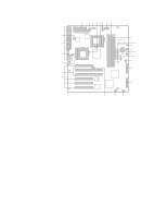
(1J15) U. CPU speed jumper block (5E1) V. 33 MHz/32-bit PCI connectors W. 66 MHz/64-bit PCI connectors X. Chassis intrusion connector (pins 1-2 of 6A) Y. System fan connector FAN1A (P11) Z. I/O ports AA. Primary processor heatsink fan connector (P12) 6 Intel Server Board STL2 Quick Start Guide - Intel STL2 | Quick Start Guide - Page 7
Back Panel Connectors C E A B DF G H I A. USB connectors B. Serial port 2 connector C. Serial port 1 connector D. NMI switch E. Parallel port connector F. Keyboard connector G. Mouse connector H. Video connector I. Network connector OM10672 Intel Server Board STL2 Quick Start Guide 7 - Intel STL2 | Quick Start Guide - Page 8
. Reserved. These pins should not be jumpered for normal operation. If these pins are jumpered, the system will attempt BIOS recovery. These pins should not be jumpered for normal operation. Reserved. These pins should be jumpered for normal operation. 8 STL2 Server Board Quick Start Guide - Intel STL2 | Quick Start Guide - Page 9
Reserved. These pins should not be jumpered for normal operation. Reserved. These pins should not be jumpered for normal operation. Reserved. These pins should not be jumpered for normal operation. NOTE: Pins 9-11 should be jumpered for normal operation. Intel Server Board STL2 Quick Start Guide 9 - Intel STL2 | Quick Start Guide - Page 10
Installing Processors If you are installing only one processor, you must install a terminator in the secondary processor socket. 1 Observe the safety and ESD precautions at the beginning of this document. 2 Raise the locking bar on the socket. OM10686 10 STL2 Server Board Quick Start Guide - Intel STL2 | Quick Start Guide - Page 11
3 Aligning the pins of the processor with the socket, insert the processor into the socket. Note what the processor speed is so you can set the jumpers correctly. 4 Close the handle completely. 2/)!% OM08879 2/)!% OM08880 Intel Server Board STL2 Quick Start Guide 11 - Intel STL2 | Quick Start Guide - Page 12
5 Place the fan heatsink on top of the processor. OM10680 12 STL2 Server Board Quick Start Guide - Intel STL2 | Quick Start Guide - Page 13
processor socket. We recommend attaching the side away from the fan cable first. Then use a screw driver or other tool to attach the remaining side. PGA370 A B 7 Connect the processor fan cable to the processor fan connector. OM10681 P36 P12 PGA370 Intel Server Board STL2 Quick Start Guide - Intel STL2 | Quick Start Guide - Page 14
933 ä ä 1000 ä Pins 11-12 9 Repeat for the second processor. The second processor must be the same speed and within one stepping of the primary processor. If you are installing two processors, skip the section titled "Install the Processor Terminator." 14 STL2 Server Board Quick Start Guide - Intel STL2 | Quick Start Guide - Page 15
processor socket. If you are installing two processors, skip this section. 1 Raise the locking bar on the socket. 2 Aligning the pins of the processor terminator with the socket, insert the terminator into the socket. 3 Close the handle completely. OM10679 Intel Server Board STL2 Quick Start Guide - Intel STL2 | Quick Start Guide - Page 16
Install the Voltage Regulator Module If you are installing two processors, you must install a voltage regulator module (VRM). Orient the VRM as shown and press it into the connector. Make sure the plastic latches engage the VRM. C B A OM10677 16 STL2 Server Board Quick Start Guide - Intel STL2 | Quick Start Guide - Page 17
the processors. Installed DIMMs must be the same speed and must all be registered. For a list of supported memory, call your service representative or visit the Intel Support website: http://support.intel.com/support/motherboards/server/STL2/compat.htm 4321 OM10673 Intel Server Board STL2 Quick - Intel STL2 | Quick Start Guide - Page 18
power supply in the back of the chassis. The shield has cutouts that match the I/O ports. 1 Install the shield from inside the chassis. Orient the shield so that the cutouts align with the corresponding I/O connectors on the server board and the parallel port. 18 STL2 Server Board Quick Start Guide - Intel STL2 | Quick Start Guide - Page 19
installed in screw holes 1, 4, 5, 6, 7, 13, 17, 18, 19. The hole numbers are stamped in the chassis sheet metal. Make sure the two positioning standoffs are in holes 17 and 19. You chassis may be different from the illustration. 1 = 4 = 5 7 17 18 6 13 Intel Server Board STL2 Quick Start Guide - Intel STL2 | Quick Start Guide - Page 20
Install the Server Board Bumpers Peel the adhesive backing from two rubber bumpers; stick the bumpers to the chassis wall. 5.250 [133.35] 8.250 [209.55] 5.250 [133.35] OM10676 20 STL2 Server Board Quick Start Guide - Intel STL2 | Quick Start Guide - Page 21
the way to properly install your server board. 1 Tilt the board into the chassis I/O connector end first. Position the board so the screw holes board is properly seated, then tighten all the screws firmly, starting with the screws in the center of the board. Intel Server Board STL2 Quick Start Guide - Intel STL2 | Quick Start Guide - Page 22
server board. 5 Connect the hot swap SCSI cable (H, if your chassis has it) to the Ultra160 LVD SCSI connector (P8) on the server board. 6 Connect the chassis intrusion cable to the pins 1-2 of block 6A (K) or pins 3-4 of jumper block 1L4 on the server board. 22 STL2 Server Board Quick Start Guide - Intel STL2 | Quick Start Guide - Page 23
are now ready to install drives into your chassis. We recommend you install drives before connecting their data cables to the server board. We recommend you connect the blue connector on the IDE cable to the server board before you connect the floppy cable. Intel Server Board STL2 Quick Start Guide - Intel STL2 | Quick Start Guide - Page 24
support.intel.com/support/motherboards/server/STL2 Telephone Talk to a Customer Support Technician* (Intel reserves the right to change pricing for telephone support of the world: Call the North American Service Center at +1-916-377-7000 (M-F, 7:00 intel.com 24 STL2 Server Board Quick Start Guide
-
 1
1 -
 2
2 -
 3
3 -
 4
4 -
 5
5 -
 6
6 -
 7
7 -
8
-
9
-
10
-
11
-
12
-
13
-
14
-
15
-
16
-
17
-
18
-
19
-
20
-
21
-
22
-
23
-
24
 |
 |

A guide for technically qualified persons
Intel
®
Server Board STL2
Quick Start Guide
Before You Begin
.....................................................................
2
Installation Notes
Installation Process Quick Reference
...........................................
4
Common Problems
.......................................................................
5
Server Board Components
............................................................
6
Back Panel Connectors
.................................................................
7
Jumpers
........................................................................................
8
Installation Procedures
Installing Processors
....................................................................
10
Install the Processor Terminator
..................................................
15
Install the Voltage Regulator Module
..........................................
16
Memory
.......................................................................................
17
Install the I/O Shield
....................................................................
18
Rearrange the Standoffs
...............................................................
19
Install the Server Board Bumpers
................................................
20
Install the Server Board
...............................................................
21
Connect Cables
............................................................................
22
Finish Setting up Your Chassis
....................................................
23
Getting Help
................................................................................
24
Translations of this guide are available at:
Übersetzungen dieses Handbuchs sind erhältlich bei:
Versiones traducidas de esta guía se encuentran disponibles en:
Des traductions de ce guide sont disponibles à l'adresse:
Le versioni tradotte di questa Guida sono disponibili presso:
As traduções deste guia estão disponíveis em:
±
±
±
±
±
±
²
Copyright © 2000 Intel Corporation.
All rights reserved.
No part of this document may be
copied, or reproduced in any form, or by any means without prior written consent of Intel.
Intel Corporation (Intel) makes no warranty of any kind with regard to this material, including,
but not limited to, the implied warranties of merchantability and fitness for a particular purpose.
Intel assumes no responsibility for any errors that may appear in this document.
Intel makes
no commitment to update nor to keep current the information contained in this document.
†
Third-party brands and trademarks are the property of their respective owners.
Order Number:
A28574-001