Intermec 6822 6820 Printer Installation Instructions - Page 9
Strip the Vehicle Battery Cable Jacket, Crimping Cable Ends, Preparing the Vehicle Battery Cable
 |
View all Intermec 6822 manuals
Add to My Manuals
Save this manual to your list of manuals |
Page 9 highlights
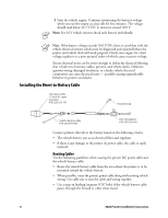
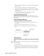
• Make sure that cable routing does not interfere with other equipment or vehicle controls. • Ensure that cable routing does not invite damage to the cable. • Secure the vehicle battery cable at least every 18" (50 cm) throughout the cable run: use adjustable clamps (provided) or wire-tie to existing vehicle cable runs. • Completely install the printer power cable and take voltage measurements before connecting the printer. Preparing the Vehicle Battery Cable After you route the vehicle battery cable to the vehicle battery, do the following to prepare the vehicle battery cable for the terminal ring and fuse link assembly. Strip the Vehicle Battery Cable Jacket To strip the gray vehicle battery cable jacket and insulation 1 Cut the gray battery cable near the battery to avoid coiling or tying excess cable. 2 Strip the battery cable jacket (gray) back 12-14" (31-36 cm). 3 Strip 1/4" (6 mm) of insulation from the black (or brown) and red wires. Gray battery cable P/N: 226-271-101 Red wire Strip each wire end 6 mm (0.25 in) Black (or brown) wire Strip each wire end 6 mm (0.25 in) Crimping Cable Ends To attach a terminal ring and a preassembled in-line fuse link to the vehicle battery cable. Note: You may have to shorten and restrip the red wire when attaching the fuse link assembly. 1 Strip the black wire. 2 Crimp the 3/8" terminal ring (P/N 809-165-001) onto the black wire. 3 Attach the fuse link assembly (P/N 315-071-002) to the red wire (if needed, shorten red wire), strip 1/4" (6 mm) of insulation off the red wire. 6820 Printer Installation Instructions 9
-
 1
1 -
2
-
3
-
 4
4 -
 5
5 -
 6
6 -
 7
7 -
 8
8 -
 9
9 -
 10
10 -
 11
11 -
 12
12 -
 13
13 -
 14
14 -
15
-
16
-
17
-
18
-
19
-
20
-
21
-
22
-
23
-
24
-
25
-
26
 |
 |
