Intermec PX4i Printer 802.11 Radio Interface Kit Installation Instructions - Page 10
Connect the light pipe to the SDIO board assembly., end of the light pipe into the back plate.
 |
View all Intermec PX4i manuals
Add to My Manuals
Save this manual to your list of manuals |
Page 10 highlights
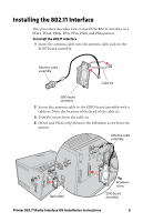
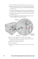
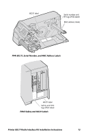
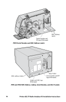
5 Insert the SDIO board assembly into the 44-pin connector. 6 (PD41 and PD42 only) Route the antenna cable behind the real-time clock board, and secure the SDIO board assembly with the screw. 7 (PF2i, PF4i, PM4i, PX4i, and PX6i) Secure the SDIO board assembly with the M3x8mm screw that shipped with the kit. 8 Install the other end of the antenna cable on the back plate and tighten the nut. 9 Insert the light pipe through the back plate, and press the end of the light pipe into the back plate. Light pipe Back plate SDIO board assembly 10 Connect the light pipe to the SDIO board assembly. 11 Use the other cable tie to secure the antenna cable and the light pipe to the printer as shown. 12 Trim the excess from the cable tie. 13 Close the printer. 14 Connect the antenna to the antenna connector on the back plate. 10 Printer 802.11 Radio Interface Kit Installation Instructions
-
 1
1 -
2
-
3
-
4
-
 5
5 -
 6
6 -
 7
7 -
 8
8 -
 9
9 -
 10
10 -
 11
11 -
 12
12 -
 13
13 -
 14
14 -
 15
15 -
16
 |
 |
