Invacare RECLSYS Owners Manual 2 - Page 60
LCD Display, Emergency Stop Reset Switch
 |
View all Invacare RECLSYS manuals
Add to My Manuals
Save this manual to your list of manuals |
Page 60 highlights
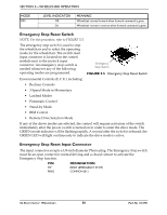
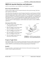
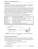
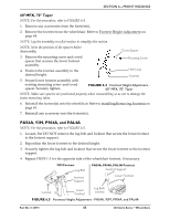
SECTION 5-WHEELCHAIR OPERATION LCD Display Located in front of the joystick, it provides information on the status of the wheelchair through a two line by twelve character length back lighted display. The LCD display is easily readable in both bright sunlight and complete darkness. During normal operation the active drive is displayed on the left half of the first line. The left half of the second line is the Battery Discharge Indicator (BDI). It provides information on the remaining charge in the batteries. At full charge, solid blocks fill in all ten segments between E (Empty) and F (Full). As the battery becomes discharged, the farthest right segments will progressively disappear a half bar at a time until no segments appear between E and F. At this level the word RECHARGE will appear on the second line to indicate that the user should charge the batteries as soon as possible. The right half of the display is the Information Center. The Information Center displays current data on the wheelchair. FIGURE 5.7 shows the factory default display. Speedometer Trip Odometer Odometer Trip Amp-Hour Meter Battery Volts Battery Current Load Test Results Current Wheelchair Speed - MPH/KMH Distance traveled since the wheelchair was last powered ON - MI/KM Total Distance Traveled (Factory Default) - MI/KM Battery Capacity consumed since the wheelchair was last powered ON - AH Current Battery Voltage - VOLT Battery Current being used - AMP Current battery condition based on a load test - BATT If a fault is detected, the cause of the fault will scroll across the second line of the display. Active Drive DRIVE 1 E oooooooooo F Battery Discharge Indicator FIGURE 5.7 MKIV-A+ Joystick Switches and Indicators - Emergency Stop Reset Input Connector Emergency Stop Reset Switch The emergency stop switch is used to stop the wheelchair and to select the operating mode for the wheelchair. The switch input connector is located on the control module next to the joystick input connector. An emergency stop switch is needed whenever any of the following operating modes are programmed: • Environmental Controls (E.C.U.) including actuator controls • 3 Speed Mode in Momentary • Latched Modes 3G Storm Series® Wheelchairs 60 Part No 1134791
-
 1
1 -
2
-
3
-
4
-
5
-
6
-
7
-
8
-
9
-
10
-
11
-
12
-
13
-
14
-
15
-
16
-
17
-
18
-
19
-
20
-
21
-
22
-
23
-
24
-
25
-
26
-
27
-
28
-
29
-
30
-
31
-
32
-
33
-
34
-
35
-
36
-
37
-
38
-
39
-
40
-
41
-
42
-
43
-
44
-
45
-
46
-
47
-
48
-
49
-
50
-
51
-
52
-
53
-
54
-
 55
55 -
 56
56 -
 57
57 -
 58
58 -
 59
59 -
 60
60 -
 61
61 -
 62
62 -
 63
63 -
 64
64 -
 65
65 -
66
-
67
-
68
-
69
-
70
-
71
-
72
-
73
-
74
-
75
-
76
-
77
-
78
-
79
-
80
-
81
-
82
-
83
-
84
-
85
-
86
-
87
-
88
-
89
-
90
-
91
-
92
-
93
-
94
-
95
-
96
-
97
-
98
-
99
-
100
-
101
-
102
-
103
-
104
-
105
-
106
-
107
-
108
-
109
-
110
-
111
-
112
-
113
-
114
-
115
-
116
-
117
-
118
-
119
-
120
-
121
-
122
-
123
-
124
-
125
-
126
-
127
-
128
-
129
-
130
-
131
-
132
 |
 |
