JVC BR-DV3000UB BR-DV3000U Pro-DV recorder 71 page instruction manual - Page 19
Setting, Connection
 |
UPC - 046838325595
View all JVC BR-DV3000UB manuals
Add to My Manuals
Save this manual to your list of manuals |
Page 19 highlights
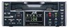
RECORDING - Connection and setting - This chapter explains the connection, setting and operation methods required to use this unit as a recorder. This unit cannot be used as an editing system recorder. Connection Ⅵ When connected to a video device equipped with a DV terminal Images can be recorded with almost no deterioration of image quality. Player DV terminal Separately available DV cable Another VTR Flow of signal DV terminal DV IN/OUT AUDIO CH 1/3 CH 2/4 LINE VIDEO Y/C OUT IN Recorder REMOTE DC12V NTSC/PAL 9PIN SERIAL NTSC PAL Monitor Memo • When signals are input from the DV terminal, the sound recording mode of the recorder is the same as that of the player. • The Date and time data from the DV terminal will be recorded. • To record the time code data from the DV terminal, set the TC DUPLICATE item of the TIME CODE menu to AUTO or NON DROP. (☞ Page 62) • For the BR-DV600 player, when the mode is changed from STILL to PLAY, the audio output will be muted for a while shortly after coming on. Thereafter, it will resume as per normal. (This does not occur with BR-DV600A.) • When it is connected to D9VTR (equipped with SA-DV60), exchanging of the date/time information is not possible. Ⅵ This unit is connected to a video device with no DV terminal (analogue input): Y/C OUT Y/C(S) video cable Video cable VIDEO OUT Audio cable VIDEO LINE IN AUDIO OUT AUDIO Y/C IN IN DV IN/OUT AUDIO CH 1/3 CH 2/4 LINE VIDEO Y/C IN OUT Player Another VTR Flow of signal Recorder REMOTE DC12V NTSC/PAL 9PIN SERIAL NTSC PAL Monitor Memo When search pictures or low-quality video signals are input, video and sound output may be temporarily distorted. Please input stable signals via a TBC, etc.. 34 Setting NTSC indicator PAL indicator OPERATE EJECT Mini A.DUB PROFESSIONAL MIC REMOTE SEL. SERIAL INPUT SEL. LINE 9PIN WIRELESS DV Y/C DVCAM NTSC PAL REC INH. CH-1/3 CH-2/4 BR-DV3000 MENIU REC PLAY PAUSE SET REW STOP FF INPUT SEL switch Rear panel DIO CH 2/4 LINE VIDEO Y/C OUT IN REMOTE DC12V NTSC/PAL 9PIN SERIAL NTSC PAL NTSC/PAL switch Memo • For DV signal input, the signal system (NTSC/PAL) is identified automatically. • For DV signal input, the AUDIO MODE item cannot be set. It will be the same mode as that of the input signal (48k or 32k). AUDIO/VIDEO menu - - -AUD I O V I DEO- - - AUD I O MODE A OUT AT SEARCH AUD I O OUT SE L AUD I O OUT L EVE L SET UP ( NTSC ) PAGE BACK 48K ON CH - 1 / 2 NORM OFF System (1/2) menu - - - SYSTEM [ 1 / 2 ] - - - STL / F . ADV BACKUP REC T I ME LONG PAUSE T I ME L ONG P AUS E MODE I NDEX WR I T E RE P E A T MODE NEXT PAGE PAGE BACK 2ND OFF 5M I N F . ADV ON BLANK Ⅵ Setting the signal system (NTSC/PAL) The signal system for analogue input is set with the NTSC/PAL switch located at the rear panel. Either the NTSC or the PAL indicator on the front lights up, depending on the setting. * Before setting the NTSC/PAL switch, please set the unit to the OPERATE OFF mode. Ⅵ Selecting the video input signal Please use the INPUT SEL. switch on the front panel. Y/C : Input Y/C separate video signals. LINE: Input composite video signals. DV : Input DV signals. Ⅵ Setting the AUDIO/VIDEO menu (☞ Page 61) • AUDIO MODE Use this menu item to set the audio sampling frequency for recording. 32k : Perform recording with an audio sampling frequency of 32kHz. Use this setting when performing audio dubbing on CH3 and CH4. 48k : Perform recording with an audio sampling frequency of 48kHz. Audio dubbing is not available. • SET UP (NTSC only) Set this item to enable/disable setup to composite signals or Y/C separate video during recording. Ⅵ Setting the SYSTEM menu (☞ Page 57) • LONG PAUSE TIME Sets the time period, after the lapse of which the unit will enter the tape protection mode when pause is activated for an extended period of time. • INDEX WRITE This setting turns on/off automatic recording of index signals when recording begins. Ⅵ Setting the time code recording during DV signal input Set the TC DUPLICATE item of the TIME CODE menu to determine whether to use the time code from the built in time code generator and clock or the data from the DV terminal. (☞ Page 62) 35
-
 1
1 -
2
-
3
-
4
-
5
-
6
-
7
-
8
-
9
-
10
-
11
-
12
-
13
-
 14
14 -
 15
15 -
 16
16 -
 17
17 -
 18
18 -
 19
19 -
 20
20 -
 21
21 -
 22
22 -
 23
23 -
 24
24 -
25
-
26
-
27
-
28
-
29
-
30
-
31
-
32
-
33
-
34
-
35
-
36
-
37
 |
 |
