JVC BR-DV3000UB BR-DV3000U Pro-DV recorder 71 page instruction manual - Page 23
PLAYBACK, Connection/setting
 |
UPC - 046838325595
View all JVC BR-DV3000UB manuals
Add to My Manuals
Save this manual to your list of manuals |
Page 23 highlights
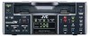
PLAYBACK - Connection/setting - This section explains the required connection, setting and operation method for using this unit as a player. Connection Ⅵ Using this unit as a standalone device DV IN/OUT AUDIO CH 1/3 CH 2/4 LINE VIDEO Y/C OUT IN REMOTE DC12V NTSC/PAL 9PIN SERIAL NTSC PAL Y/C OUT VIDEO LINE OUT AUDIO OUT Y/C (S) video cable Video cable Audio cable Monitor Ⅵ Connecting this unit to a video device with a DV terminal It can record with almost no loss in image or sound quality. DV terminal DV cable (available separately) DV terminal Monitor DV IN/OUT AUDIO CH 1/3 CH 2/4 LINE VIDEO Y/C OUT IN REMOTE DC12V NTSC/PAL 9PIN SERIAL NTSC PAL Player: the rear panel of the main unit Another VTR Memo • If the recorder is a GY-DV500 or GY-DV700W, and BR-DV3000 is put to PLAY from the STOP mode, the phase of the EE audio output from the camcorder will be displaced. There is no problem with the recorded signals. • For GY-DV300E, GY-DV500E and GY-DV700W, DV input is not possible. ( E model only ) Ⅵ Connecting this unit to a video device with no DV terminal (analogue signal): Player: the rear panel of the main unit Monitor DV IN/OUT AUDIO CH 1/3 CH 2/4 LINE VIDEO Y/C Another VTR IN REMOTE DC12V NTSC/PAL OUT 9PIN SERIAL NTSC PAL Y/C (S) OUT Y/C IN Y/C (S) video cable VIDEO LINE OUT Video cable AUDIO OUT Audio cable VIDEO AUDIO IN IN 42 Setting OPERATE Mini A.DUB PROFESSIONAL MIC REMOTE SEL. INPUT SEL. SERIAL LINE 9PIN WIRELESS DV Y/C DVCAM NTSC PAL REC CH-1/3 CH-2/4 BR-DV3000 Ⅵ REMOTE SEL. switch on the front panel To use the wireless remote controller, set the switch to WIRELESS. Memo To control the unit with the 9 PIN REMOTE or the SERIAL REMOTE terminal, set the REMOTE menu item to ON. REMOTE SEL. switch SYSTEM (1/2) Menu - - - SYSTEM [ 1 / 2 ] - - - STL / F . ADV BACKUP REC T I ME LONG PAUSE T I ME L ONG P AUS E MODE I NDEX WR I T E RE P E A T MODE NEXT PAGE PAGE BACK 2ND OFF 5M I N F . ADV ON BLANK AUDIO/VIDEO Menu AUD I O V I DEO AUD I O MODE A OUT AT SEARCH AUD I O OUT SE L AUD I O OUT L EVE L SET UP ( NTSC ) PAGE BACK 48K ON CH - 1 / 2 NORM OFF Memo AUDIO OUT SEL or AUDIO OUT LEVEL items can also be set via the AUDIO OUT SEL or AUDIO OUT LEV button on the wireless remote controller. Ⅵ SYSTEM menu • STL/F.ADV MODE Use this to select the image type for still image playback or frame advance playback. (Field image, 1st field image, 2nd field image and frame image) Note: Still images can also be selected with the STILL MODE button of the wireless remote controller. • LONG PAUSE TIME Use this menu item to set the time interval, after the lapse of which, the unit will go into the tape protection mode. (5, 3, 2 or 1 minute, 30 seconds) • LONG PAUSE MODE Use this mode to select the operation state when tape protection mode is engaged after an extended period of being in the STILL mode. (F.ADV or STBY-OFF) • REPEAT MODE Use this menu item to turn ON/OFF the REPEAT PLAYBACK function or select the type of REPEAT PLAYBACK. To disable REPEAT PLAYBACK, set it to OFF. (OFF, INDEX, VIDEO END, TAPE END) Ⅵ AUDIO/VIDEO menu • A. OUT AT SEARCH Use this menu item to turn ON/OFF audio output during variable speed playback. • AUDIO OUT SEL Use this menu item to select the output audio channel when playing tapes recorded in the 32kHz mode. (CH1/2, CH3/4, MIX) • AUDIO OUT LEVEL Use this menu item to select the audio output level (NORM, ATT). Set it to ATT when playing tapes recorded at -12dB with consumer DV devices. • SETUP (NTSC only) Use this setting to determine whether to apply the setups to the composite video or Y/C separate video output signals. 43
-
 1
1 -
2
-
3
-
4
-
5
-
6
-
7
-
8
-
9
-
10
-
11
-
12
-
13
-
14
-
15
-
16
-
17
-
 18
18 -
 19
19 -
 20
20 -
 21
21 -
 22
22 -
 23
23 -
 24
24 -
 25
25 -
 26
26 -
 27
27 -
 28
28 -
29
-
30
-
31
-
32
-
33
-
34
-
35
-
36
-
37
 |
 |
