JVC BR-DV3000UB BR-DV3000U Pro-DV recorder 71 page instruction manual - Page 7
Names And Functions, Of Various Parts, Front Panel - br b professional dv recorder
 |
UPC - 046838325595
View all JVC BR-DV3000UB manuals
Add to My Manuals
Save this manual to your list of manuals |
Page 7 highlights
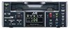
NAMES AND FUNCTIONS OF VARIOUS PARTS - Front panel - 2 1 OPERATE Mini A.DUB PROFESSIONAL MIC REMOTE SEL. INPUT SEL. SERIAL LINE 9PIN WIRELESS DV Y/C DVCAM NTSC PAL REC INH. CH-1/3 CH-2/4 BR-DV3000 EJECT MENIU REC PLAY PAUSE SET REW STOP FF 43 1 [OPERATE] Operate button/LED ● Press this button to turn on the power and operate the unit. (Operate ON) Press this button again to turn off the power. (Operate OFF) ● The OPERATE LED lights up as follows. Operate ON : the LED lights up green Operate OFF : the LED lights up red VTR error : the LED blinks in red Memo ● When the DC IN MODE item of the SYSTEM menu is set to "OPE ON" and power is supplied to the 1 [DC IN] terminal located at the rear panel, the unit goes into the OPERATE ON state even if this button is not pressed. ● Even when the power has been turned off with this button, a small amount of electricity will still be channeled into the unit. Therefore, if the unit is not going to be used for a long period of time, please remove the AC adapter to reduce energy consumption. 2 Cassette slot ● Load a cassette into or unload it from the slot. Please insert a standard DV or a mini DV cassette. ☞ Page 30 ● When the unit is in the OPERATE OFF state and if a cassette is loaded, it goes into the ON state. 3 [A. DUB] Audio dubbing button/LED ● Press this button for audio dubbing (after-recording). For audio dubbing, set the AUDIO MODE item of the AUDIO/VIDEO menu to "32K". Sound produced by the 6 MIC terminal or the 9 AUDIO IN terminal at the rear panel is recorded on CH3 and CH4 channels. ● During audio dubbing, the A. DUB LED lights up red. ● If the INPUT SEL switch is set at DV, audio dubbing is not possible. ☞ Page 39, "Audio dubbing" 4 [INPUT SEL] Input video signal se- lection switch ● Select the video signal input with this switch. Y/C : YC separate video signals from the Y/ C IN terminal LINE : composite video signals from the LINE IN terminal DV : DV signals from the DV IN/OUT terminal (IEEE1394) Note During recording, please do not manipulate this switch. Even if you do, it will not work. 10 OPERATE Mini A.DUB PROFESSIONAL MIC REMOTE SEL. INPUT SEL. SERIAL LINE 9PIN WIRELESS DV Y/C DVCAM NTSC PAL REC INH. CH-1/3 CH-2/4 BR-DV3000 EJECT MENIU REC PLAY PAUSE SET REW STOP FF 7 6 5 5 [REMOTE SEL.] Remote select switch Use this switch to select the remote controller type. 9 PIN : Select this to use the RS-422Acompatible editing remote controller (RM-G820) that connects to the 4 9 PIN REMOTE termi- nal located at the rear panel. Please use this unit as a player. * This setting is valid only when the REMOTE item of the REMOTE menu is set to ON. SERIAL : Select this to use the serial remote controller (RM-G30) that connects to the 3 SERIAL RE- MOTE terminal located at the rear panel. * This setting is valid only when the REMOTE item of the REMOTE menu is set to ON. WIRELESS : Select this to use the provided wireless remote controller. Memo ● When 9 PIN or SERIAL is selected, the buttons on the unit you wish to render operable can be selected from the LOCAL FUNCTION item of the REMOTE menu. ☞ Page 59 ● During OPERATION LOCK, this switch will not be effective. ● Control via the DV IN/OUT terminal is possible (ie unaffected by the switch setting). 6 [MIC] Microphone input terminal This is the mini jack for monaural microphone input. When this terminal is connected to a microphone, sound input via the AUDIO IN terminal located on the rear panel is not recorded. Sound from this terminal is recorded on CH1/ CH2 in the RECORD mode and CH3/CH4 in the AUDIO DUBBING mode. 7 [EJECT] Eject button ● Press this button to eject the cassette. Memo It takes about 6 seconds for the cassette to be ejected. ● If no cassette is loaded and this button is pressed for at least 2 seconds, a menu will be displayed on the monitor connected to the VIDEO LINE OUT or Y/C OUT terminal. ● When the menu is displayed, pressing this button will resume the usual screen. ☞ Page 54, "Setting the menu" 11
-
 1
1 -
 2
2 -
 3
3 -
 4
4 -
 5
5 -
 6
6 -
 7
7 -
 8
8 -
 9
9 -
 10
10 -
 11
11 -
 12
12 -
13
-
14
-
15
-
16
-
17
-
18
-
19
-
20
-
21
-
22
-
23
-
24
-
25
-
26
-
27
-
28
-
29
-
30
-
31
-
32
-
33
-
34
-
35
-
36
-
37
 |
 |
