JVC BR-DV6000U User Manual - Page 28
Yconnection
 |
UPC - 046838325557
View all JVC BR-DV6000U manuals
Add to My Manuals
Save this manual to your list of manuals |
Page 28 highlights
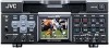
CONNECTION - Connecting video signals - Video output, e.g., VCR Input Composite DV Y/C Component Synchronization signal generator BB signal VIDEO LINE Y/C COMPONENT IN R-Y B-Y Y OUT REMOTE2 IN OUT AUDIO CH 1/3 CH 2/4 IN MONITOR OUT SIGNAL GND DC12V SYNC IN IN DV IN/OUT OUT TIME CODE IN OUT OFF REC PLAY SERIAL REMOTE TIMER OUT MONITOR OUT REMOTE1 Y/C DV MONITOR OUT (Composite) SYNC IN Monitor Composite Component Output Video output, e.g., VCR Ⅵ Output signal When BR-DV6000 enters the STOP, REC or EDIT mode, the input signal (E-E image) is output. In the PLAYBACK mode (including the playback of the pre-roll part during editing), playback images are output. However, in the edit mode with analog input, signals cannot be output to the DV OUT terminal properly. ● Analog signal • LINE OUT terminal (BNC): composite signal. • Y/C OUT terminal (4-PIN): YC separate sig- nal. When a wide screen ID signal exists in the video signal, the ID signal is output. • COMPONENT OUT terminal (BNCן3): Component (Y/B-Y/R-Y) signals are output. The output level is of ß cam (HIGH). ● Digital signal • DV IN/OUT terminal: it outputs IEEE1394compliant digital video signals. When a wide screen ID signal exists in the video signal, the ID signal is output. ● Connection with a monitor TV A monitor TV can be connected to the MONITOR OUT terminal. Besides the composite video signals, it also displays the on-screen display for status or menu screen. Memo Set PB/DV IN in the SYSTEM (2/2) Menu screen according to the signal format of the tape to be played. (NTSC or PAL) Ⅵ Input signal The input video signal is selected with the INPUT SELECT switch on the front panel. Set VIDEO INPUT SEL in the VIDEO Menu screen to select YC input or component input. ● Analog signal • LINE IN terminal (BNC): composite signal • Y/C IN terminal (4-PIN): YC separate signal When a wide screen ID signal is being input, the ID signal is recorded. • COMPONENT IN terminal (BNCן3): The component (Y/B-Y/R-Y) signal. The output level is of ß cam (HIGH). ● Digital signal • DV IN/OUT terminal : IEEE1394-compliant digital video signals are input. When a wide screen ID signal is being input, the ID signal is recorded. Set PB/DV IN in the SYSTEM (2/2) Menu screen according to the signal format to be input to the DV terminal. (NTSC or PAL). Memo Whether or not to enable SET UP for analog I/O signals of signals can be selected with SET UP in the VIDEO Menu screen (for NTSC only). 28
-
 1
1 -
2
-
3
-
4
-
5
-
6
-
7
-
8
-
9
-
10
-
11
-
12
-
13
-
14
-
15
-
16
-
17
-
18
-
19
-
20
-
21
-
22
-
 23
23 -
 24
24 -
 25
25 -
 26
26 -
 27
27 -
 28
28 -
 29
29 -
 30
30 -
 31
31 -
 32
32 -
 33
33 -
34
-
35
-
36
-
37
-
38
-
39
-
40
-
41
-
42
-
43
-
44
-
45
-
46
-
47
-
48
-
49
-
50
-
51
-
52
-
53
-
54
-
55
-
56
-
57
-
58
-
59
-
60
-
61
-
62
-
63
-
64
-
65
-
66
-
67
-
68
-
69
-
70
-
71
-
72
-
73
-
74
-
75
-
76
-
77
-
78
-
79
-
80
-
81
-
82
-
83
-
84
-
85
-
86
-
87
-
88
-
89
-
90
-
91
-
92
-
93
-
94
-
95
-
96
-
97
-
98
-
99
-
100
-
101
-
102
-
103
-
104
-
105
-
106
 |
 |
