JVC C205U Instruction Manual - Page 7
Installation and connection - parts
 |
UPC - 046838021497
View all JVC C205U manuals
Add to My Manuals
Save this manual to your list of manuals |
Page 7 highlights
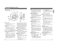
Installation and connection About Connection Cables • Turn OFF the power supply to all components before making connections. Ⅲ Video signal cables Connect the coaxial cables (BNC) to the video signal output connector (BNC). Note Use the 3C-2V or 5C-2V video signal cable (coaxial cable). The 7C-2V cannot be used. To Video Signal Cable To DC 12 V or AC 24 V Power Supply Ⅲ DC 12 V or AC 24 V power supply cable Connect the DC 12 V or the AC 24 V power supply to the DC 12V/AC 24V terminals on the terminal board. To prevent connection errors or a cable disconnection, we recommend the use of lug plates for the connections. The following table shows the connection distances and connection cables provided that 2-conductor VVF cables (vinyl-insulated vinyl sheath cables) are used. Maximum extension (reference) 100 m 260 m 410 m 500 m Conductor diameter 1.0ømm 1.6ømm 2.0ømm 2.6ømm and more and more and more and more CLASS 2 ONLY (U TYPE) ISOLATED POWER ONLY (E TYPE) BLACK WIRE - AC24V 1 2 LW40459-001A RED WIRE + DC12V BNC Cable - VIDEO OUT SEE INSTRUCTION MANUAL CAUTION: • If thin cables are used (i.e. with a high resistance), a significant voltage drop will occur when the unit is at its maximum power consumption. Either use a thick cable to restrict the voltage drop at the camera side to below 10%, or place the power supply near to the camera. If voltage drop occurs during operation, the performance will be unstable. • Attach the cable conductors so that they do not come into contact with the drop prevention wires. • Do not allow input from both a DC 12 V and AC 24 V power supply at the same time. • When using a DC 12 V power supply, ensure that the polarities of the cable are correct. • The AC 24 V power supply should conform to the following: U-type: Class 2 only E-type: Isolated power supply only E-10 Mounting the Camera to the Ceiling 1. 2. LABEL TURN PULL Cable extraction hole 3. φ140 4. To the ceiling slab, etc. 5. 4 inch square electrical box 6. Drop prevention wire Video signal cable 8. Power supply cable 7. Solder or caulk Insulation tape 1. Remove the dome cover Hold the bottom of the unit and turn the dome cover counterclockwise. 2. Pull the label part downwards and remove the dome cover. 3. Open a hole of ø140mm in the ceiling. MEMO There is no need to open a hole in the ceiling when extracting the cables from the cable extraction hole on the camera side. (੬ See page 8) 4. Mount the electrical box. This unit can be mounted with a 4 inch square electrical box. For mounting an electrical box, consult your dealer of purchase. 5. Mount the drop prevention wire. In order to prevent the unit from falling for any reason, connect the drop prevention wire to the ceiling slab, etc. 6. Pull out the cables from the ceiling. Before connecting, pull out the power supply and video signal cables about 10cm from the electrical box. 7. Connect the power supply cable. When installing, cover the cable with insulation tape so that it does not become damaged from contact with surrounding parts. In addition, be sure to use a wiring cable for the power supply cable. 8. Connect the video signal cable (BNC connector). E-11 English
-
 1
1 -
 2
2 -
 3
3 -
 4
4 -
 5
5 -
 6
6 -
 7
7 -
 8
8 -
 9
9 -
 10
10
 |
 |
