JVC C205U Instruction Manual - Page 8
Mounting the Camera to the Ceiling Continued, Connection for Adjustment of the Camera, Adjusting
 |
UPC - 046838021497
View all JVC C205U manuals
Add to My Manuals
Save this manual to your list of manuals |
Page 8 highlights
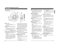
Installation and connection Mounting the Camera to the Ceiling (Continued) 9. BNC connector Power supply cable Roll with tape 9. Roll cables with insulation tape. As shown in the diagram to the left, roll the entire connecting section of the power supply cable and BNC connector with insulation tape and insert them in the electrical box. 4 inch square electrical box MEMO Rolling cables with insulation tape not only increases the work efficiency later on, but reduces the entry of noise, etc. 10.Adjust the unit in the direction to shoot. 11.When using an electrical box, use the 2 mounting holes to fix the box to the unit. Mounting holes 10. Shooting direction 11. Screws Mounting holes CAUTION: • Do not hold the lens part when mounting the unit to the ceiling or wall. • When directly mounting the unit to the ceiling or wall, fix the unit using all 4 mounting holes. • Use M4 screws or bolts for attaching the ceiling mount. • If wood screws are used, use screws with a diameter of 4.1 mm. Connection for Adjustment of the Camera Temporarily used for making various adjustments while the camera remains in the installed location. FOCUS ADJ. OFF OFF OFF AUTO LL PHASE ON ON-AGC ON-BLC MANU INT WHT.BAL. R B SPOT RESET CORRECTION Setting switch Adjustment button L H IRIS LEVEL IRIS LEVEL Volume FOR SERVICE MONITOR 75Ω termination disconnected Monitor TV * The power to the camera body must be ON when adjustments are performed. E-12 Adjusting the Camera Angle Tilt lock screws Horizontal Lock screw Variable range 120˚ L LEVEIRLIS H MONITOR SERFVOIRCE CORRECSTPIOOTN RESET PHASE R AUTO LL B OFF OFF OFF FOCUS ADJ. WHTI.NBTALM. ANOUN-BOLNC-AOGNC 50˚ 80˚ Vertical rotation Ⅲ Horizontal rotation (adjustable range: 120°) 1. Loosen the horizontal LOCK screw. 2. Holding the both tilt lock screws, rotate horizontally. 3. Tighten the horizontal LOCK screw. Ⅲ Vertical rotation (adjustable range: +80°, -50°) 1. Loosen the tilt lock screws. 2. Holding the rotation levers, rotate vertically. 3. Tighten the tilt lock screws. Rotation levers Ⅲ Image inclination (adjustable range: ±15°) Manipulate the rotation levers to adjust the inclination of the image. Ⅲ Adjusting the image size Adjust the size using the zoom ring. Zoom ring Focus ring Tilt lock screws Ⅲ Adjusting the focus Adjust using the focus ring. When adjusting the focus, set the FOCUS ADJ. switch to "ON". After adjustment is completed, set the FOCUS ADJ. switch to "OFF". When required, the surveillance image should be adjusted, etc. E-13 English
-
 1
1 -
2
-
 3
3 -
 4
4 -
 5
5 -
 6
6 -
 7
7 -
 8
8 -
 9
9 -
 10
10
 |
 |
