JVC C215V4U Instruction Manual - Page 25
Connecting to the DC12 V power supply, About the power cable - vn cameras
 |
UPC - 046838030185
View all JVC C215V4U manuals
Add to My Manuals
Save this manual to your list of manuals |
Page 25 highlights
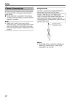
Connecting to the DC12 V power supply Connect this product to the DC12 V power supply when not using the PoE. Connect the polarity correctly. Red : DC12V+ Black : DC12V- Note: ● Make sure to select only one mode of electrical supply. Connecting the power cable and the LAN cable for the PoE at the same time may result in failure or malfunction of the camera. Wind the waterproof tape. Power cable Black: DC12 V- Solder or crimp Red: DC12 V+ Solder or crimp Insulation tape Insulation tape Warning The rated power of this product is DC12 V. Make sure to use it with the correct voltage. Supplying a power different from the rated value may result in failures and in the worst scenario, smoking and fire. Memo: ● In a system where multiple units of VNC215V4U are used, turn on the power of only 1 unit to configure the IP address settings via the Internet Explorer. Upon doing so, turn on the power of the second unit and configure accordingly. Configure the camera settings using the same procedure. ● Whenever duplication of IP addresses occurs, check that there is only one VNC215V4U under the same LAN environment and wait for at least 10 minutes. Access to VN-C215V4U may be denied unless you restore the power supply of all network devices under the same LAN environment. ● To use AA-P700 in the power supply unit, connect one unit of this product. Also refer to the AA-P700 instruction manual. Memo: About the power cable ● When using 2-core VVF (Vinyl-insulated vinyl-sheath cable), the connection distance is as follows: (Reference value) Maximum 40 extension (m) Conductor R1.0 and Diameter (mm) above 120 R1.6 and above 190 R2.0 and above 25
-
 1
1 -
2
-
3
-
4
-
5
-
6
-
7
-
8
-
9
-
10
-
11
-
12
-
13
-
14
-
15
-
16
-
17
-
18
-
19
-
 20
20 -
 21
21 -
 22
22 -
 23
23 -
 24
24 -
 25
25 -
 26
26 -
 27
27 -
 28
28 -
 29
29 -
 30
30 -
31
-
32
-
33
-
34
-
35
-
36
-
37
-
38
-
39
-
40
-
41
-
42
-
43
-
44
-
45
-
46
-
47
-
48
-
49
-
50
-
51
-
52
-
53
-
54
-
55
-
56
-
57
-
58
-
59
-
60
-
61
-
62
-
63
-
64
-
65
-
66
-
67
-
68
-
69
-
70
-
71
-
72
-
73
-
74
-
75
-
76
-
77
-
78
-
79
-
80
-
81
-
82
-
83
-
84
-
85
-
86
 |
 |
