JVC DLA-HD10KSU DLA-HD10K Owner's Manual (50 pages) - Page 12
Rear Side/Right Side, Controls and Features continued
 |
View all JVC DLA-HD10KSU manuals
Add to My Manuals
Save this manual to your list of manuals |
Page 12 highlights
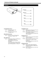
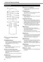
Controls and Features (continued) Rear Side/Right Side D EF G SCREEN TRIGGER SERVICE RS-232C H DVI B Removing the control panel cover Release Lock C A A Control Panel Cover Remove this cover when operating this unit or when replacing the lamp unit. ● Unlock the cover, followed by sliding it downwards to remove it. ● Please refer to page 13 for details on the control panel. Handling the Control Panel Cover ● The gap between this unit and the control panel cover is narrow. Be careful not to stick your finger into the gap between this unit and the control panel cover. ● Be careful of the protrusions and corners of components to avoid injury. ● After attaching the control panel cover, check that the lock is fastened. The control panel cover may drop and cause injury. B Exhaust Vent Warm air is expelled through this vent to keep the system cool. Do not block the exhaust vents. This may cause the unit to malfunction. C AC Power Input Terminal This is the AC power input terminal. Connect the supplied cord to this terminal. (A Page 25) D Remote Sensor (Rear) When operating with the remote control, aim it towards the sensor. (A Page 23) ● A remote sensor is also located at the front of the unit. 12 E SCREEN TRIGGER Terminal This terminal is used for controlling the SCREEN TRIGGER-compatible elevating screen. An output at DC +12 V/100 mA (max.) is produced when the power is on. ● Consult a qualified technician for a connection with the screen. F [SERVICE] Terminal This terminal is intended for servicing purposes. Do not use it. Using it may give rise to error and malfunction of the unit. G [RS-232C] Terminal (D-sub 9 Pin) This is the RS-232C interface-specific terminal. This unit can be controlled by a computer connected externally. (A Pages 24, 45) ● For details, please check with your authorized dealer. H [DVI] Terminal (DVI-D 24 Pin) This is an input terminal for video signals. Video signals that can be input are 1080/50p and 1080/60p signals. (A Page 24)
-
 1
1 -
2
-
3
-
4
-
5
-
6
-
 7
7 -
 8
8 -
 9
9 -
 10
10 -
 11
11 -
 12
12 -
 13
13 -
 14
14 -
 15
15 -
 16
16 -
 17
17 -
18
-
19
-
20
-
21
-
22
-
23
-
24
-
25
-
26
-
27
-
28
-
29
-
30
-
31
-
32
-
33
-
34
-
35
-
36
-
37
-
38
-
39
-
40
-
41
-
42
-
43
-
44
-
45
-
46
-
47
-
48
-
49
-
50
 |
 |
