JVC FS-S77 Instructions - Page 60
manuals since the terminal names actually printed on the rear
 |
UPC - 046838015069
View all JVC FS-S77 manuals
Add to My Manuals
Save this manual to your list of manuals |
Page 60 highlights
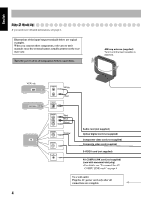
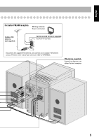
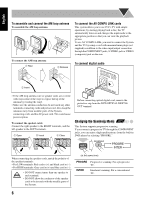
English Step 3: Hook Up If you need more detailed information, see page 6. Illustrations of the input/output terminals below are typical examples. When you connect other components, refer also to their manuals since the terminal names actually printed on the rear may vary. Turn the power off to all components before connections. AM loop antenna (supplied) Turn it until the best reception is obtained. VCR, etc. AUX DECODER TV 4 AUDIO OUT OPTICAL DIGITAL IN White Red VIDEO INPUT PR PB Y VIDEO INPUT VIDEO INPUT AV COMPU LINK Red Blue Green Yellow Audio cord (not supplied) Optical digital cord (not supplied) Component video cord (not supplied) Composite video cord (supplied) S-VIDEO cord (not supplied) AV COMPU LINK cord (not supplied) (cord with monaural mini plug) • For details, see "To connect the AV COMPU LINK cords" on page 6. To a wall outlet Plug the AC power cord only after all connections are complete.
-
 1
1 -
2
-
3
-
4
-
5
-
6
-
7
-
8
-
9
-
10
-
11
-
12
-
13
-
14
-
15
-
16
-
17
-
18
-
19
-
20
-
21
-
22
-
23
-
24
-
25
-
26
-
27
-
28
-
29
-
30
-
31
-
32
-
33
-
34
-
35
-
36
-
37
-
38
-
39
-
40
-
41
-
42
-
43
-
44
-
45
-
46
-
47
-
48
-
49
-
50
-
51
-
52
-
53
-
54
-
 55
55 -
 56
56 -
 57
57 -
 58
58 -
 59
59 -
 60
60 -
 61
61 -
 62
62 -
 63
63 -
 64
64 -
 65
65 -
66
-
67
-
68
-
69
-
70
-
71
-
72
-
73
-
74
-
75
-
76
-
77
-
78
-
79
-
80
-
81
-
82
-
83
-
84
-
85
-
86
-
87
-
88
-
89
-
90
-
91
-
92
-
93
-
94
-
95
-
96
-
97
-
98
-
99
-
100
-
101
-
102
-
103
 |
 |
