JVC GY-HD250U 117 page operator's manual for the GY-HD250U - Page 16
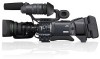
Rear - gy hd250 camera
 |
UPC - 046838027383
View all JVC GY-HD250U manuals
Add to My Manuals
Save this manual to your list of manuals |
Page 16 highlights
e_hd250.book Page 12 Tuesday, October 24, 2006 3:11 PM CONTROLS, INDICATORS AND CONNECTORS Rear Section „ Connecting the Earphone Cable To reduce the emission of unwanted radio waves, be sure to attach the provided clamp filter as shown in the figure below. • Attach the clamp filter as close to this device as possible, as shown in the figure. 1 2 3 4 1Back tally lamp This lamp lights up when the GY-HD250/GY-HD251 enters the record mode. It blinks during the transition to the record mode. When the tape has run out, or the VTR enters the warning mode, it blinks quickly. • Use the BACK TALLY item on the OTHERS[1/2] menu screen to select whether or not the lamp should light and the lighting pattern. X See page 96. 2[PHONES] Earphone jack This is a stereo mini-jack for connecting an earphone for audio monitoring. Plug in an earphone or headphone with a 3.5 mm diameter plug. The earphone can also be used to monitor alarm tones in accordance with the circumstances. The audio channel to be output is selected with the AUDIO MONITOR item on the AUDIO/MIC[2/2] menu screen and MONITOR SELECT switch d on page 19. The audio output level is adjusted with the Audio monitor volume control 3 on page 14. MEMO • The volume of the alarm sound is set with the ALARM VR LEVEL item on the OTHERS[1/2] menu screen. • When using a stereotype jack and stereo sound should be output, the following setting should be performed. Set the MONITOR SELECT switch d on page 19 to BOTH. Set the AUDIO MONITOR item on the AUDIO/MIC[2/2] menu screen to STEREO. Earphone cable Clamp filter 3Shoulder belt hooks Allows you to attach a separately sold shoulder belt. 4LCD monitor Shows a color camera image or the VTR playback picture. It is also used for displaying the following: • Menu Setting screens • Characters showing the whether the GY-HD250/GYHD251 is set to shooting mode or VTR playback mode • Date and time and time code • Audio level meter • Warning indications, etc. X See page 22. 12
-
 1
1 -
2
-
3
-
4
-
5
-
6
-
7
-
8
-
9
-
10
-
 11
11 -
 12
12 -
 13
13 -
 14
14 -
 15
15 -
 16
16 -
 17
17 -
 18
18 -
 19
19 -
 20
20 -
 21
21 -
22
-
23
-
24
-
25
-
26
-
27
-
28
-
29
-
30
-
31
-
32
-
33
-
34
-
35
-
36
-
37
-
38
-
39
-
40
-
41
-
42
-
43
-
44
-
45
-
46
-
47
-
48
-
49
-
50
-
51
-
52
-
53
-
54
-
55
-
56
-
57
-
58
-
59
-
60
-
61
-
62
-
63
-
64
-
65
-
66
-
67
-
68
-
69
-
70
-
71
-
72
-
73
-
74
-
75
-
76
-
77
-
78
-
79
-
80
-
81
-
82
-
83
-
84
-
85
-
86
-
87
-
88
-
89
-
90
-
91
-
92
-
93
-
94
-
95
-
96
-
97
-
98
-
99
-
100
-
101
-
102
-
103
-
104
-
105
-
106
-
107
-
108
-
109
-
110
-
111
-
112
-
113
-
114
-
115
-
116
-
117
 |
 |
