JVC KD-X320BTS Instruction Manual - Page 31
Part list for, installation, Wiring connection
 |
View all JVC KD-X320BTS manuals
Add to My Manuals
Save this manual to your list of manuals |
Page 31 highlights
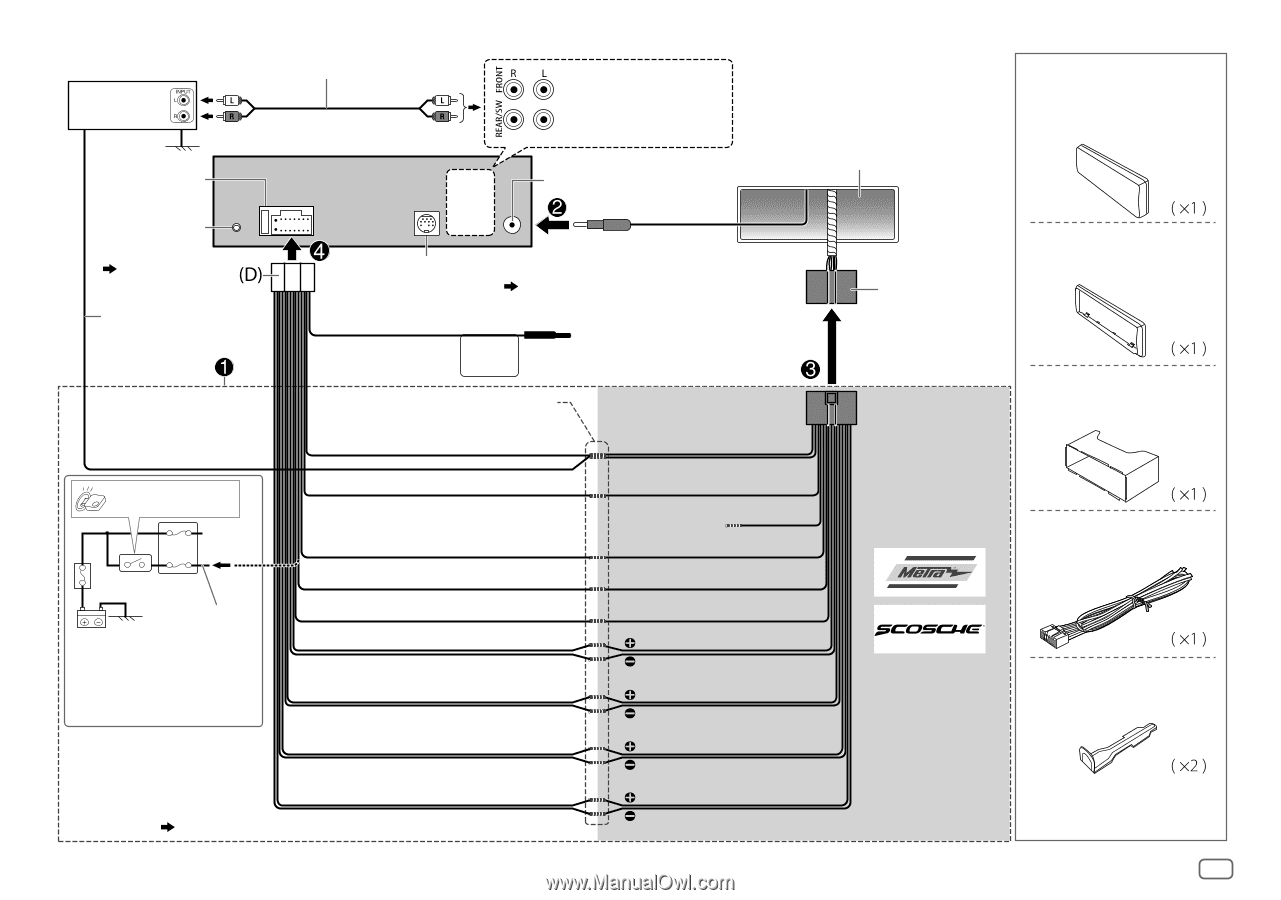
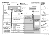
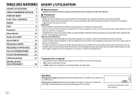
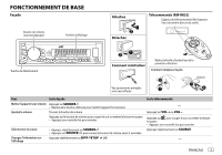
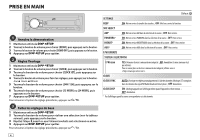
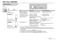
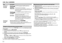
Wiring connection JVC Amplifier*1 Signal cord (not supplied) Front output Rear/subwoofer output *1 Firmly connect the ground wire of the amplifier to the car's chassis to avoid damaging the unit. Part list for installation (A) Faceplate Fuse (10 A) Antenna terminal Vehicle dashboard MIC (Microphone input terminal) ( 14) Remote wire (not supplied) Ignition switch Car fuse block Separate red wire Make this connection if your vehicle factory wiring harness does not have "12 V ignition switch" wire. *2 You can also connect a subwoofer speaker directly using this lead without an external subwoofer amplifier. For setting, 21. To the optional SiriusXM Vehicle Tuner (commercially available) ( 11) Light blue/yellow STEERING WHEEL REMOTE To the steering wheel remote control adapter Join the same color wires together. Blue/white: Remote (200 mA max.) Orange/white: Illumination Recommended connection Blue: To power antenna Blue/white: To amplifier Yellow: Battery 12 V (Not used) Brown Red: Ignition 12 V Black: Ground Gray: Front speaker (right) Gray/black White: Front speaker (left) White/black Purple: Rear speaker (right) Purple/black Green: Rear speaker (left)*2 Green/black *2 Factory wiring harness (vehicle) (B) Trim plate (C) Mounting sleeve Vehicle-specific Wiring Harness (separately purchased) (D) Wiring harness For more information: Metra Electronics: www.metraonline.com Scosche Industries: www.scosche.com (E) Extraction key ENGLISH 29
-
 1
1 -
2
-
3
-
4
-
5
-
6
-
7
-
8
-
9
-
10
-
11
-
12
-
13
-
14
-
15
-
16
-
17
-
18
-
19
-
20
-
21
-
22
-
23
-
24
-
25
-
 26
26 -
 27
27 -
 28
28 -
 29
29 -
 30
30 -
 31
31 -
 32
32 -
 33
33 -
 34
34 -
 35
35 -
 36
36 -
37
-
38
-
39
-
40
-
41
-
42
-
43
-
44
-
45
-
46
-
47
-
48
-
49
-
50
-
51
-
52
-
53
-
54
-
55
-
56
-
57
-
58
-
59
-
60
-
61
-
62
-
63
-
64
-
65
-
66
-
67
-
68
-
69
-
70
-
71
-
72
-
73
-
74
-
75
-
76
-
77
-
78
-
79
-
80
-
81
-
82
-
83
-
84
-
85
-
86
-
87
-
88
 |
 |