JVC KY-F560U KA-F5602U, KA-F5603U Studio kit for KY-F560U camera (47 page inst - Page 9
Precautions, Regarding Gain-lock Signal and adjustment of System Phase
 |
UPC - 046838326004
View all JVC KY-F560U manuals
Add to My Manuals
Save this manual to your list of manuals |
Page 9 highlights
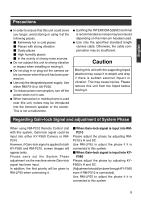
English Precautions ⅷ In order to ensure that this unit could serve you longer, avoid storing or using it at the following places. Ⅵ Extremely hot or cold places Ⅵ Places with strong vibration Ⅵ Dusty places Ⅵ High humidity places Ⅵ In the vicinity of strong noise sources ⅷ Do not subject this unit to strong vibration or impact when installing or moving it. ⅷ Do not plug in or plug out the camera cable connector when this unit has been powered on. ⅷ Use only the designated power supply. Use either RM-P210 or AA-P250. ⅷ To reduce power consumption, turn off the power when not in-use. ⅷ When transceiver or mobile phone is used near this unit, noises may be introduced into the intercom speaker or the screen. This is not a malfunction. ⅷ Earthing the INTERCOM G(GND) terminal is recommended as noises may be induced depending on the intercom headset used. ⅷ Use only the specified standard length camera cable. Otherwise, the cable compensation may be insufficient. Caution Moving this unit with the supporting tripod attached may cause it to detach and drop if there is sudden external impact or vibration. This may cause injuries. Please remove this unit from the tripod before moving it. Regarding Gain-lock Signal and adjustment of System Phase When using RM-P210 Remote Control Unit with this system, Gain-lock signal could be input into either KY-F560 Camera or RMP210. However, if Gain-lock signal is applied to both KY-F560 and RM-P210, screen images will appear jerky. Please carry out the System Phase adjustment via the machine where Gain-lock signal has been input. In addition, the first priority will be given to RM-LP55 when connecting it. Ⅵ When Gain-lock signal is input into RMP210 Please adjust the phase by adjusting RMP210's H and SC. Use RM-LP55 to adjust the phase if it is connected to this system. Ⅵ When Gain-lock signal is input into KY- F560 Please adjust the phase by adjusting KYF560's H and SC. (Adjustment should be done through KY-F560 even if RM-P210 is connected). Use RM-LP55 to adjust the phase if it is connected to this system. 9
-
 1
1 -
2
-
3
-
 4
4 -
 5
5 -
 6
6 -
 7
7 -
 8
8 -
 9
9 -
 10
10 -
 11
11 -
 12
12 -
 13
13 -
 14
14 -
15
-
16
-
17
-
18
-
19
-
20
-
21
-
22
-
23
-
24
-
25
-
26
-
27
-
28
-
29
-
30
-
31
-
32
-
33
-
34
-
35
-
36
-
37
-
38
-
39
-
40
-
41
-
42
-
43
-
44
-
45
-
46
-
47
 |
 |
