JVC TK-AM200U TK-AM200 Dome CCTV Camera Instruction Manual (748KB) - Page 17
JVC TK-AM200U - Active Movement Color Dome Camera Manual
 |
View all JVC TK-AM200U manuals
Add to My Manuals
Save this manual to your list of manuals |
Page 17 highlights
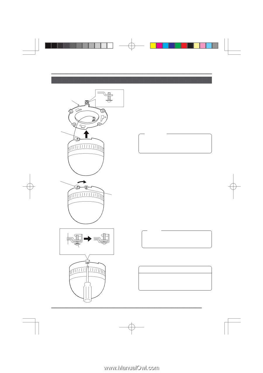
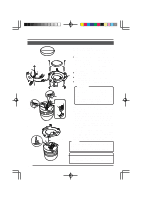
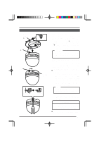
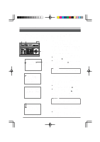
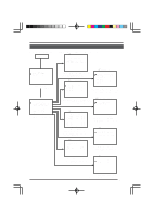
Changing Camera Settings Using the RM-P2580 Menu Operations When the RM-P2580 is used as the remote control unit, the camera's built-in menus can be called up and set from the remote control unit. This function is explained on this page. (For details, refer to the Instruction Manual for the remote control unit.) MENU SET button button REMOTE CONTROL UNIT RM-P2580 CAMERA POWER SET ALARM KEY LOCK AUTO F-1 F-2 F-3 POSITION Power switch on the rear panel. 1. 2. SETUP MENU LENS SPEED CAMERA/POSITION PAN/TILT POSITION 1 OPEN 2 5 8 0 /HOME 3 6 9 ENTER CAMERA CLOSE IRIS 4 7 CLEAR OPTION 1 OPTION 2 NEAR FOCUS AF FAR AUTO PAN AUTO PATROL WIDE ZOOM TELE PAN/TILT control lever 3. RM-P2580 SE TUP POS I T I ON SE T U P . . C AME R A . . CON T RO L UN I T . . Item cursor Submenu to be followed 4. Set the power switch on the rear panel of the remote control unit to ON. When the MENU button is pressed for about 3 seconds, the LED lights up and the remote control's SETUP screen will be output from the MONITOR OUTPUT-1 connector. Use the PAN/TILT control lever to move the cursor (>) and align it the CAMERA item. ● The cursor will move up when the lever is pressed up ( ). ● The cursor will move down when the lever is pressed down ( ). Press the SET button to display the SETUP screen of the camera. Memo: SETUP screen from the remote control SE TUP C A M E R A MO D E S E L E C T . . C AME R A V I D EO A D J U S T . . V I DEO A D J FOR POS I . . TEXT ED I T . . A U TO P A T RO L S E T . . AU TO PAN SE T . . P A N I C A L A RM S E T . . F A C T OR Y S E T T I NGS . . Items followed by ".." are items that have a submenu. 5. 6. Camera SETUP screen C A M E R A MO D E S E L E C T V . PHASE 127 P O S . T E X T L OC . UP - L A LM . TEX T S I Z E DOU B L E B LC ED I T 1 . . B LC ED I T 2 . . Select the item in the same manner as in step 3. Press the PAN/TILT control lever to the left or to the right to change the set value of the selected item. ● The value will become smaller when the lever is pressed to the left ( ). ● The value will become larger when the lever is pressed to the right ( ). When the set value of an item is changed, the change mark (∗) shown in the illustration on the left appears. Submenu sample screen Change mark C A M E R A MO D E S E L E C T V . PHASE 127 P O S . T E X T L OC . UP - R A LM . TEX T S I Z E DOU B L E B LC ED I T 1 . . B LC ED I T 2 . . Memo: For details on submenu settings, see the next and following pages. 7. Sample screen after change When changes have been made, press the MENU button to return to the higher order menu. ● At this point, "DATA SAVED" is displayed on the screen for about 3 seconds when item settings have been changed. 18
-
 1
1 -
2
-
3
-
4
-
5
-
6
-
7
-
8
-
9
-
10
-
11
-
 12
12 -
 13
13 -
 14
14 -
 15
15 -
 16
16 -
 17
17 -
 18
18 -
 19
19 -
 20
20 -
 21
21 -
 22
22 -
23
-
24
-
25
-
26
-
27
-
28
-
29
-
30
-
31
-
32
-
33
-
34
-
35
 |
 |