JVC TK-AM200U TK-AM200 Dome CCTV Camera Instruction Manual (748KB) - Page 21
JVC TK-AM200U - Active Movement Color Dome Camera Manual
 |
View all JVC TK-AM200U manuals
Add to My Manuals
Save this manual to your list of manuals |
Page 21 highlights
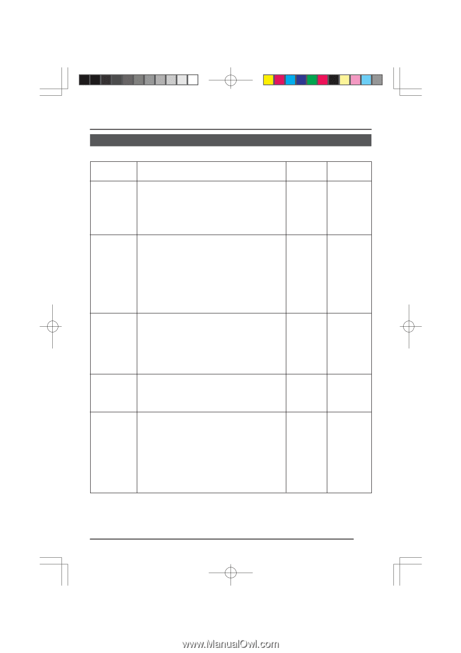
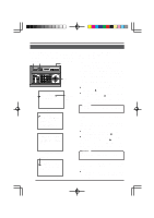
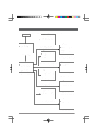
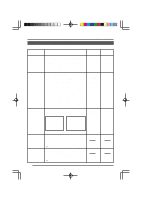
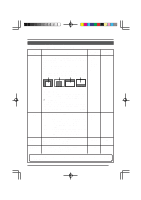
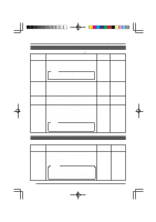
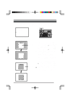
Changing Camera Settings Using the RM-P2580 CAMERA VIDEO ADJUST Screen (Continued) Item COLOR LEVEL Function Used to adjust the color level of the video signal. • To make colors lighter ...Decrease the value. • To make colors darker ...Increase the value. Pressing the SET button displays the AWC (One-push Auto White Balance) adjustment screen. See "AWC ADJUST Screen" below. Variable range 0 10 ~ (Integer steps) Factory setting 5 AWC ADJUST AWC ADJUST Screen The white balance compensation values set on this screen are retained in camera body. To use the saved white balance compensation values, set the W. BALANCE item on the VIDEO ADJUST FOR POSI screen to AWC. ( See page 23.) 1. AWC AD J US T 2. AD JU ST STAR T > SET 3. AWC ADJUST screen A WC OK Normal screen 4. Select the AWC ADJUST item on the CAMERA VIDEO ADJUST screen. When the SET button is pressed, the AWC ADJUST screen is displayed. Pressing the SET button on the AWC ADJUST screen starts AWC (white balance adjustment). When AWC adjustment is completed normally, the compensation values are retained in the camera body, and "AWC OK" is displayed on the screen for about 3 seconds before the AWC ADJUST screen returns. The following indications are displayed if the AWC adjustment is not accomplished correctly. • OBJECT NG (improper object) • HIGH LIGHT ERROR (excessive illumination) • LOW LIGHT ERROR (insufficient illumination) To cancel the AWC operation, press the MENU button before the operation is completed normally. CAUTION: • Even when the VIDEO ADJUST FOR POSI screen's W. BALANCE item is set to "ATW" or "MANUAL", the AWC adjustment on the AWC ADJUST screen is effective and the value resulting from the AWC adjustment is stored in the camera body. However, when the positions set by "ATW" or "MANUAL" are selected again, the image returns from the setting determined by the value resulting from the AWC adjustment to the setting values of "ATW" or "MANUAL", respectively. • AWC adjustment works separately for each position but only one adjustment value is stored, and the value stored in the camera body is the value obtained when AWC adjustment was last performed. 22
-
 1
1 -
2
-
3
-
4
-
5
-
6
-
7
-
8
-
9
-
10
-
11
-
12
-
13
-
14
-
15
-
 16
16 -
 17
17 -
 18
18 -
 19
19 -
 20
20 -
 21
21 -
 22
22 -
 23
23 -
 24
24 -
 25
25 -
 26
26 -
27
-
28
-
29
-
30
-
31
-
32
-
33
-
34
-
35
 |
 |