JVC TK-C1530U Instructions - Page 51
COMMUNICATION screen, Functions and settings, STYLE, MACHINE ID
 |
UPC - 046838027925
View all JVC TK-C1530U manuals
Add to My Manuals
Save this manual to your list of manuals |
Page 51 highlights
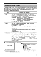
COMMUNICATION screen This item sets the control signal connection terminals at the back of the camera. If the setting is changed, be sure to close the menu screen before switching on the power again. The screen display when power is switched on differs according to the setting of this item. Item Functions and settings TYPE This sets whether the communication with the control device is bi-directional or unidirectional. Select the setting according to the device to be connected. SIMPLEX : Select this to connect an unidirectional communication control device. DUPLEX : Select this to connect a bi-directional communication control device. [Default setting: DUPLEX] STYLE This sets a communication system. Select the setting according to the system used. P TO P (Point to Point) :This is set when a remote control unit controls a camera. MULTIDROP :This is set when a remote control unit controls multiple cameras. [Default setting: P TO P] MACHINE ID This is set when the STYLE item is set to AMULTIDROPB. This number identifies individual cameras in a group. This item does not operate properly if an ID number is repeated within a system. When used in combination with RM-P2580E, set the item together with the VIDEO INPUT number of RM-P2580E. When STYLE item is set to P TO P, A- - -B will be displayed and settings is disabled. [Setting: 1 to 99] Ⅵ Screen display when power is switched on Monitor screen PROTOCOL : DUPLEX ID-05 TYPE display Only displayed when the STYLE item is MULTIDROP Memo: ● Only the following 4 types are displayed. ● DUPLEX ● DUPLEX ID-TT ● SIMPLEX ● SIMPLEX ID-TT (TT indicates that MACHINE ID setting is required) 51
-
 1
1 -
2
-
3
-
4
-
5
-
6
-
7
-
8
-
9
-
10
-
11
-
12
-
13
-
14
-
15
-
16
-
17
-
18
-
19
-
20
-
21
-
22
-
23
-
24
-
25
-
26
-
27
-
28
-
29
-
30
-
31
-
32
-
33
-
34
-
35
-
36
-
37
-
38
-
39
-
40
-
41
-
42
-
43
-
44
-
45
-
 46
46 -
 47
47 -
 48
48 -
 49
49 -
 50
50 -
 51
51 -
 52
52 -
 53
53 -
 54
54 -
 55
55 -
 56
56 -
57
-
58
-
59
-
60
-
61
-
62
-
63
-
64
-
65
-
66
-
67
-
68
-
69
-
70
 |
 |
