JVC VN-C10U VN-C10U User Manual (32 pages) - Page 8
Controls, Connectors and Indicators, Front, top and side views
 |
View all JVC VN-C10U manuals
Add to My Manuals
Save this manual to your list of manuals |
Page 8 highlights
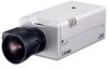
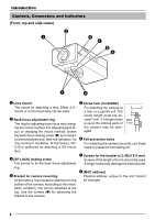
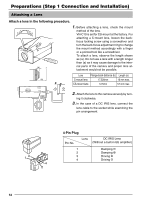
Introduction Controls, Connectors and Indicators (Front, top and side views) 2 1 34 5 8 7 6 1 Lens mount The mount for attaching a lens. Either a Cmount or a CS-mount lens can be used. 2 Back-focus adjustment ring The ring for adjusting back-focus and changing the mount method. For adjusting back-focus or changing the mount method, loosen the back-focus locking screw (3) by turning it counterclockwise and, after the operation, fix it by turning it clockwise. At the factory, VNC10 is optimized for attaching a CS mount lens. 3 [BF LOCK] locking screw This serves to fix the back focus-adjustment ring. 4 Bracket for camera mounting. At the factory, the bracket is attached on the bottom of the camera. According to the installation condition, this can be attached at the top. Use the screws (7) for attaching the bracket to the camera. 5 Screw hole (1/4-20UNC) For attaching the camera to a fixer or a pan/tilt unit. The screw length must not exceed 7 mm. If a longer screw is used, the internal parts of the camera may be damaged. MAX. 7 mm 6 Fall-preventive holes For installing the camera securely, use these holes to prevent it from falling off. 7 Screws for the bracket (x 2: M2.6 X 6 mm) Screws of the length of 6 mm should be used. A longer screw may damage the internal parts. 8 [MAC address] Physical address unique to the unit. Cannot be changed. 8
-
 1
1 -
2
-
 3
3 -
 4
4 -
 5
5 -
 6
6 -
 7
7 -
 8
8 -
 9
9 -
 10
10 -
 11
11 -
 12
12 -
 13
13 -
14
-
15
-
16
-
17
-
18
-
19
-
20
-
21
-
22
-
23
-
24
-
25
-
26
-
27
-
28
-
29
-
30
-
31
-
32
 |
 |
