JVC XA-GP1BK Instruction Manual - Page 8
How to Mount the Infrared Address Transmitter
 |
View all JVC XA-GP1BK manuals
Add to My Manuals
Save this manual to your list of manuals |
Page 8 highlights
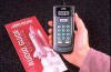
How to Mount the Infrared Address Transmitter (XA-GT1TN) The Infrared Address Transmitter can be secured to either a cable or a ceiling railing. Settings for each switch 1 Setting the address • Set the desired address with the rotary switch. (000 - 255) Regarding connections to the power source Example: Connect to standard household power outlet or a ceiling outlet with a safety plug. Power adaptor (sold separately) Slotted screwdriver used for clocks (2 mm diameter - sold separately) 2 Setting the Auto/Point switch • To enter the Auto • Set the switch to "A" Start mode Auto. A P • To enter the Pointing mode A P • Set the switch to "P" Point 3 Setting the Master/Slave switch • The switch is now set to "M" master. M S Connect to DC12V/0.4A 8
-
 1
1 -
2
-
 3
3 -
 4
4 -
 5
5 -
 6
6 -
 7
7 -
 8
8 -
 9
9 -
 10
10 -
 11
11 -
 12
12 -
 13
13 -
14
-
15
-
16
-
17
-
18
-
19
-
20
-
21
-
22
-
23
-
24
-
25
-
26
-
27
 |
 |
