Jenn-Air JGRP436HL Installation Instructions - Page 18
Adjusting Simmer Low and Main Low Settings
 |
View all Jenn-Air JGRP436HL manuals
Add to My Manuals
Save this manual to your list of manuals |
Page 18 highlights
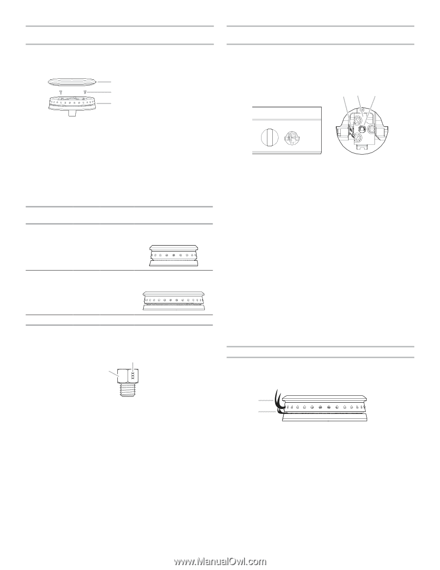
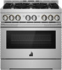
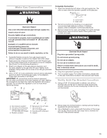
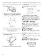
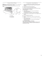
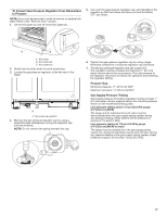
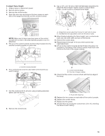
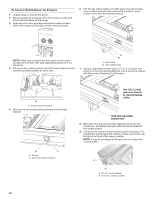
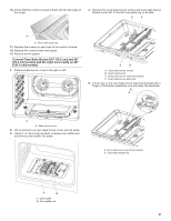
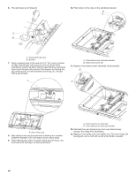
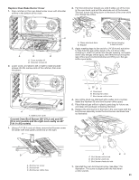
To Convert Surface Burners from Natural Gas to Propane 1. If the burner grates are installed, remove them. 2. Remove burner cap. 3. Remove the burner base by first removing (2) T-20 screws. A Burner B A. Burner cap B. Screws C C. Burner base 4. Apply masking tape to the end of a 1/4" (6.4 mm) nut driver to help hold the gas orifice spud in the nut driver while changing it. Insert nut driver into the gas opening and press down onto the gas orifice spud and remove by turning the gas orifice spud counterclockwise and lifting out. Set gas orifice spud aside. 5. Replace with correct Propane gas orifice spud. See the "Propane Gas Orifice Spud/Hood Chart". Use the following chart to find the exact orifice spud placement. Propane Gas Orifice Spud/Hood Chart Burner Rating Stamp Size Burner Style 7,400 BTUs 70 44 0.70 mm Small burner - main 0.44 mm Small burner - simmer 13,000 BTUs 99 50 0.99 mm Large burner - main 0.50 mm Larger burner - simmer 16,000 BTUs 116 1.16 mm Grill burner NOTE: Refer to serial tag for more information on burner ratings and locations. Burner orifice spud A B A. Size stamp B. Fuel type stamp (L or N) 6. Place Natural gas orifice in plastic parts bag for future use and keep with package containing literature. NOTE: There may be extra orifices in your kit. 7. Replace the burner base and screws. Tighten screws only until burner is snug to cooktop, do not over-tighten. 8. Replace burner cap. 9. Repeat steps 2 through 8 for the remaining burners. Adjusting Simmer Low and Main Low Settings on Surface Burner for Propane 1. Remove the surface burner control knobs and bezels (oven control knobs and griddle control knobs do not have to be removed). 2. Locate the Simmer low-turndown adjustment screw through the bezel on the left side of the ignition switch. AB C A. Simmer low-turndown adjustment screw B. Ignition switch C. Main low-turndown adjustment screw (inside stem) 3. With the burner ON, and set to Simmer Lo, adjust the simmer flame down to the proper BTU level. Using a 1/8" x 4¼" (3.2 mm x 108 mm) flat blade screwdriver, turn the simmer low-turndown adjustment screw clockwise until the flame height is below the bottom of the cap. If the flame becomes unstable and flickers or appears to race around the burner, the adjustment is too low and the screw should be adjusted counterclockwise until the flame is stable. Repeat this step for all surface burners, except the grill burner. NOTE: Use a knob to adjust the burner valve. NOTE: If your range has the IR grill, then skip ahead to the Convert IR Grill Burner section. NOTE: Adjust each burner individually. 4. With burner OFF, using the same flat blade screwdriver, turn the main low-turndown adjustment screw 120-135 degrees clockwise. This will set the main low burner rate to a proper level. 5. Replace the bezels using the 2 screws which attach to the valve brackets. 6. Push the surface knobs onto the valve stems. 7. Replace burner grates. Flame Height The cooktop flame should be a steady blue flame approximately 1/4" (6.4 mm) high. Burner A B A. Upper (main) flame B. Lower (simmer) flame 18
-
 1
1 -
2
-
3
-
4
-
5
-
6
-
7
-
8
-
9
-
10
-
11
-
12
-
 13
13 -
 14
14 -
 15
15 -
 16
16 -
 17
17 -
 18
18 -
 19
19 -
 20
20 -
 21
21 -
 22
22 -
 23
23 -
24
-
25
-
26
-
27
-
28
-
29
-
30
-
31
-
32
-
33
-
34
-
35
-
36
-
37
-
38
-
39
-
40
-
41
-
42
-
43
-
44
-
45
-
46
-
47
-
48
-
49
-
50
-
51
-
52
-
53
-
54
-
55
-
56
-
57
-
58
-
59
-
60
-
61
-
62
-
63
-
64
-
65
-
66
-
67
-
68
-
69
-
70
-
71
-
72
 |
 |