Jensen UMP9020 Owners Manual - Page 4
Wiring - speakers
 |
View all Jensen UMP9020 manuals
Add to My Manuals
Save this manual to your list of manuals |
Page 4 highlights
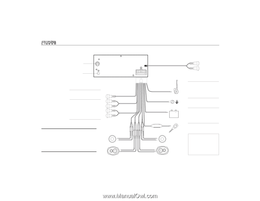
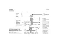
WIRING CD Changer Connector Antenna Connector 15 Subwoofer Output Connect to optional subwoofer. Amplifier Wiring Connect line out for Rear optional external amplifiers. The red connector is for the right Front and the white connector is for the left. Blue Gray Brown CAUTION: Failure to wire exactly as shown may cause electrical damage to the radio. WARNING! Never combine (bridge) outputs for use with 1 speaker. WARNING! Never ground negative speaker leads to chassis ground. LF/AVG White/Black (-) LR/ARG White (+) Green/Black (-) Green (+) 4 Blue Black Yellow + Red 0.5A Gray/Black (-) Gray (+) Violet/Black (-) Violet (+) RF/AVD RR/ARD UMP9020 Auxiliary Input Power Antenna Connect to power antenna or amplifier. If not used, tape bare end of wire. Ground Connect to ground terminal. Memory/Battery Connect to battery or 12 volt power source that is always live. The radio will not work if this wire is not connected. Accessory/Ignition Connect to existing radio wire or radio fuse. Fuses When replacing a fuse, make sure the new fuse is the correct type and amperage (15 amp ATO). Using an incorrect fuse could damage the radio.
-
 1
1 -
 2
2 -
 3
3 -
 4
4 -
 5
5 -
 6
6 -
 7
7 -
 8
8 -
 9
9 -
 10
10 -
11
-
12
-
13
-
14
-
15
-
16
-
17
-
18
-
19
-
20
-
21
-
22
-
23
-
24
-
25
-
26
-
27
-
28
-
29
-
30
-
31
-
32
-
33
-
34
-
35
-
36
-
37
-
38
-
39
-
40
-
41
-
42
-
43
-
44
-
45
-
46
-
47
-
48
-
49
-
50
-
51
-
52
-
53
-
54
-
55
-
56
-
57
-
58
-
59
 |
 |