Kenmore 33968 Owners Manual - Page 13
etc.tocontrol
 |
View all Kenmore 33968 manuals
Add to My Manuals
Save this manual to your list of manuals |
Page 13 highlights
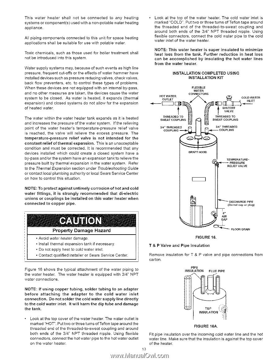
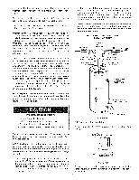
Thiswaterheatershallnotbe connectetdo anyheating systemosrcomponentu(s)edwithanon-potabwleatehr eating appliance. Allpipingcomponenctosnnectetodthisuniftorspaceheating applicatiosnhsalbl esuitablfeorusewithpotablweater. Toxichemicalssu, chasthoseusedforboiletrreatmensthall notbeintroduceindtothissystem. Watesrupplsyystemms ayb, ecausoefsucheventasshighline pressurfere, quenctut-offosrtheeffectosfwatehr ammehrave installeddevicessuchaspressureducinvgalvesc,hecvkalves, backflowpreventerest,c.to controtlhesetypesof problems. Whenthesedeviceasrenotequippewdithaninternably-pass, andnoothemr easureasretakent,hedevicecsausethewater systemto beclosed.Aswaterisheatedit, expand(sthermal expansioann) dclosedsystemdsonotallowfortheexpansion ofheatewd ater. Thewatewr ithinthewaterheatetrankexpandassitisheated andincreasethsepressuroefthewatesrystemI.ftherelieving pointof thewaterheater'tsemperature-presrseulireefvalve is reachedth, evalvewill relievetheexcesspressureT.he temperature-pressruelrieef valve is not intended for the constant relief of thermal expansion. This is an unacceptable condition and must be corrected. It is recommended that any devices installed which could create a closed system have a by-pass and/or the system have an expansion tank to relieve the pressure built by thermal expansion in the water system. Refer to the Thermal Expansion section under Troubleshooting Guide or contact local plumbing authority or local Sears Service Center on how to control this situation. Look at the top of the water heater. The cold water inlet is marked "COLD". Put two or three turns of Teflon tape around the threaded end of the threaded-to-sweat coupling and around both ends of the 314" NPT threaded nipple. Using flexible connectors, connect the cold water pipe to the cold water inlet of the water heater. NOTE: This water heater is super insulated to minimize heat loss from the tank. Further reduction in heat loss can be accomplished by insulating from the water heater. the hot water lines INSTALLATION COMPLETED USING INSTALLATION KiT FLEXIBLE WATER CONNECTORS HOT WATER ____ODTLET COLD WATER ,j2% T CODPUNG_ DRAFT HOOD COUPLING "4F--'--PTREENSPSEURRAETURE" RELIEF VALVE NOTE: To protect against untimely corrosion of hot and cold water fittings, it is strongly recommended that di-electric unions or couplings be installed on this water heater when connected to copper pipe. __R _'--_ DISCHARGE PIPE {Do net cap or plug) Property Damage Hazard • Avoid water heater damage. • Install thermal expansion tank if necessary. . Do not apply heat to cold water inlet. . Contact qualified installer or Sears Service Center. Figure 16 shows the typical attachment of the water piping to the water heater. The water heater is equipped with 3/4" NPT water connections. '_"-_ FIGURE 16. FLOOR DRAIN T & P Valve and Pipe insulation Remove insulation for T & P valve and pipe connections carton. PiPE iNSULATION FLUE PiPE from NOTE: If using copper tubing, solder tubing to an adapter before attaching the adapter to the cold water inlet connection. Do not solder the cold water supply line directly to the cold water inlet. It will harm the dip tube and damage the tank. Look at the top cover of the water heater. The water outlet is marked "HOT". Put two or three turns of Teflon tape around the threaded end of the threaded-to-sweat coupling and around FIGURE 16A. both ends of the 3/4" NPT threaded nipple. Using flexible connectors, connect the hot water pipe to the hot water outlet on the water heater. Fit pipe insulation over the incoming cold water line and the hot water line. Make sure that the insulation is against the top cover of the heater. 13
-
 1
1 -
2
-
3
-
4
-
5
-
6
-
7
-
 8
8 -
 9
9 -
 10
10 -
 11
11 -
 12
12 -
 13
13 -
 14
14 -
 15
15 -
 16
16 -
 17
17 -
 18
18 -
19
-
20
-
21
-
22
-
23
-
24
-
25
-
26
-
27
-
28
-
29
-
30
 |
 |