Kenmore 33968 Owners Manual - Page 14
FitT&Pvalve
 |
View all Kenmore 33968 manuals
Add to My Manuals
Save this manual to your list of manuals |
Page 14 highlights
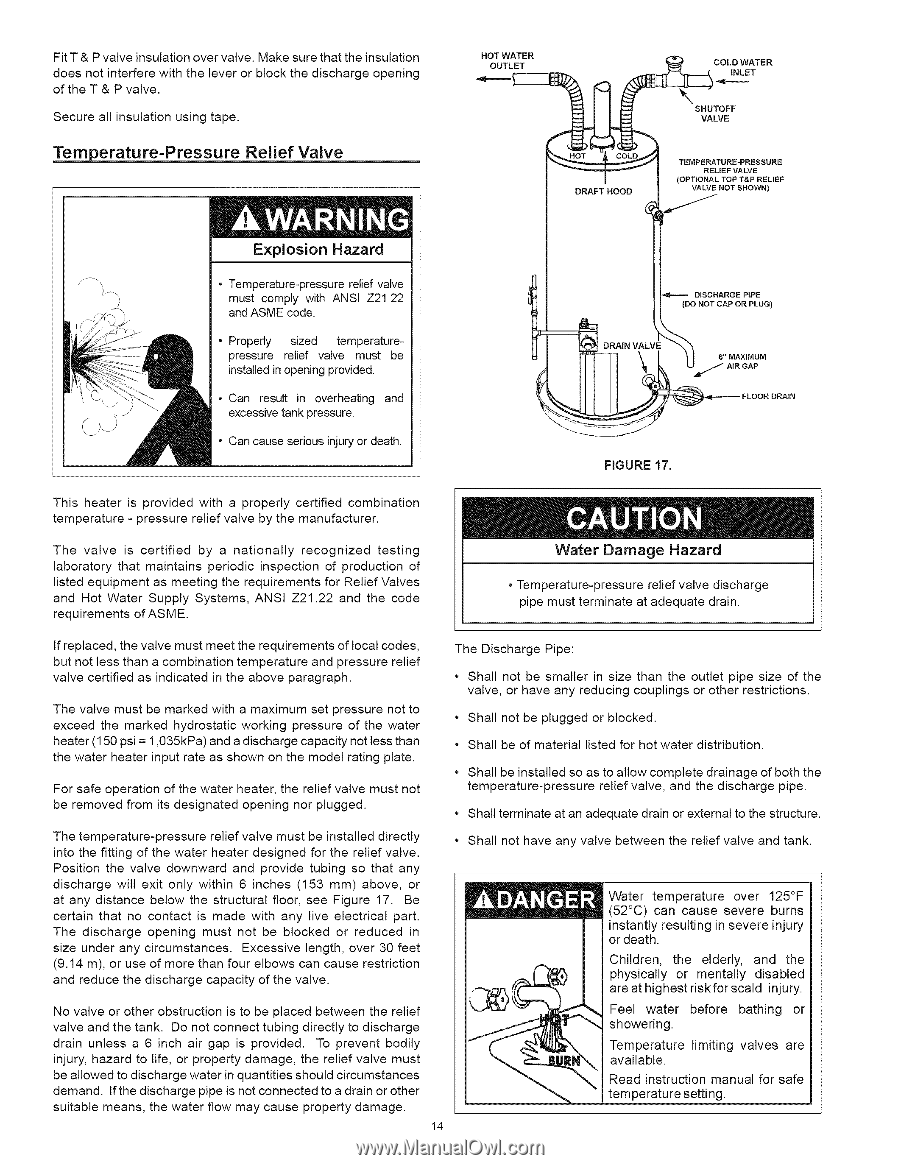
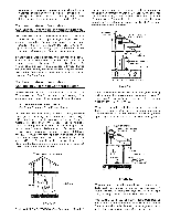
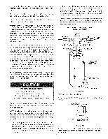
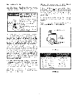
FitT&Pvalveinsulatioonvevr alveM. akesurethatheinsulation doesnotinterferweiththeleveor rblockthedischargoepening oftheT&Pvalve. Securaellinsulatiounsingtape. Temperature=Pressure Relief Valve HOT WATER OUTLET DRAFT HOOD COLD WATER INLET SHUTOFF VALVE TEMPERATURE-PRESSURE RELIEF VALVE (OPTIONAL TOP T&P RELIEF VALVE NOT SHOWN) Explosion Hazard = Temperature-pressure relief valve must comply with ANSI Z21.22 • J,!_. and ASME code. - Properly sized temperaturepressure relief valve must be installed in opening provided. • Can result in overheating and excessive tank pressure. - Can cause serious injury or death. (DO NOT CAP OR PLUG) FIGURE 17, FLOOR DRAIN This heater is provided with a properly certified combination temperature - pressure relief valve by the manufacturer. The valve is certified by a nationally recognized testing laboratory that maintains periodic inspection of production of listed equipment as meeting the requirements for Relief Valves and Hot Water Supply Systems, ANSI Z21.22 and the code requirements of ASME. Water Damage Hazard o Temperature-pressure relief valve discharge pipe must terminate at adequate drain. If replaced, the valve must meet the requirements of local codes, but not less than a combination temperature and pressure relief valve certified as indicated in the above paragraph. The valve must be marked with a maximum set pressure not to exceed the marked hydrostatic working pressure of the water heater (150 psi = 1,035kPa) and a discharge capacity not less than the water heater input rate as shown on the model rating plate. For safe operation of the water heater, the relief valve must not be removed from its designated opening nor plugged. The Discharge Pipe: • Shall not be smaller in size than the outlet pipe size of the valve, or have any reducing couplings or other restrictions. • Shall not be plugged or blocked. • Shall be of material listed for hot water distribution. • Shall be installed so as to allow complete drainage of both the temperature-pressure relief valve, and the discharge pipe. • Shall terminate at an adequate drain or external to the structure. The temperature-pressure relief valve must be installed directly into the fitting of the water heater designed for the relief valve. Position the valve downward and provide tubing so that any discharge will exit only within 6 inches (153 mm) above, or at any distance below the structural floor, see Figure 17. Be certain that no contact is made with any live electrical part. The discharge opening must not be blocked or reduced in size under any circumstances. Excessive length, over 30 feet (9.14 m), or use of more than four elbows can cause restriction and reduce the discharge capacity of the valve. • Shall not have any valve between the relief valve and tank. Water temperature over 125°F (52°C) can cause severe burns instantly resulting in severe injury or death. Children, the elderly, and the physically or mentally disabled are at highest risk for scald injury. No valve or other obstruction is to be placed between the relief valve and the tank. Do not connect tubing directly to discharge drain unless a 6 inch air gap is provided. To prevent bodily injury, hazard to life, or property damage, the relief valve must be allowed to discharge water in quantities should circumstances demand. If the discharge pipe is not connected to a drain or other suitable means, the water flow may cause property damage. 14 Feel water before bathing or showering. Temperature limiting valves are available. Read instruction manual for safe temperature setting.
-
 1
1 -
2
-
3
-
4
-
5
-
6
-
7
-
8
-
 9
9 -
 10
10 -
 11
11 -
 12
12 -
 13
13 -
 14
14 -
 15
15 -
 16
16 -
 17
17 -
 18
18 -
 19
19 -
20
-
21
-
22
-
23
-
24
-
25
-
26
-
27
-
28
-
29
-
30
 |
 |