Kenmore 75251 Owners Manual - Page 5
Installation, Requirements - manual
 |
View all Kenmore 75251 manuals
Add to My Manuals
Save this manual to your list of manuals |
Page 5 highlights
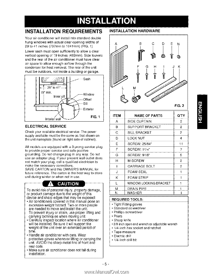
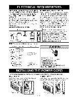
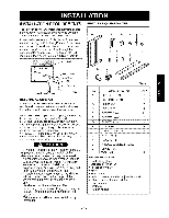
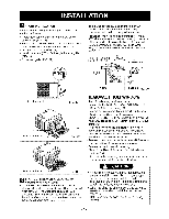
INSTALLATION REQUIREMENTS Your air conditioner will install into standard double hung windows with actual clear opening widths of 29 to 41 inches (737mm to 1041mm) (FIG. 1) Lower sash must open sufficiently to albw a clear vertical opening of 19 inches (483mm). Side louvers and the rear of the air conditioner must have clear air space to allow enough airflow through the _ndenser for heat removal. The rear of the unit must be outdoors, not inside a buiiding or garage. INSTALLATION HARDWARE A B C D EN F GH I JK 19" rain. Inner Exterior Interior wall FIG, 1 ELECTRICAL SERVICE Check your available electrical service. The power supply available must be the same as that shown on the unit n_eplate (found on right: side of cabinet). AH mode_s are equipped with a 3-prong service plug to provide proper service and safe positive grounding_ Do not change plug in any way, Do not use an adapter plug. If your present wall outlet does not match your plug, call a qualified electrician to make the necessary corrections. SAVE CARTON and this OWNER'S MANUAL for future reference. The carton is the best way to store unit during winter or when not in use. To avoid risk of personal injury, property damage, or product damage due to the weight of this device and sharp edges that may be exposed: • Air _nditioners covered in this manual pose an excessive weight hazard. Two or more people are ne_ed to move and install the unit. To prevent injury or strain, use proper li_ing and carrying techniques when moving unit. • Carefully inspect location where air _nditioner will be installS. Be sure it will support the weight of the unit over an extended peri_ of time. • Handle air _nditioner with care. Wear protective gloves whenever lifting or car_ing the unit. AVOID the sharp metal fins of front and rear coils. • Make sure air conditioner does not fali during installation. FIG. 2 ITEM A B C D E F G H I J K L M N NAME OF PARTS SIDE CURTAIN SUPPORT BRACKET SILL BRACKET LOCK NUT SCREW: 25/64" SCREW: 13/16" SCREW: 9/16" M-SCREW CARRIAGE BOLT FOAM SEAL FOAM STRIP WINDOW LOCKINGBRACKET DRAIN PiPE WASHER Q'TY 2 2 2 4 11 7 5 2 2 1 1 1 1 1 REQUIRED TOOLS: • Tight Fi_ing gloves • Standard screwdriver • Phillips screwdriver • Pliers • Sharp knife ° 3/8-inch o_n end wrench or adjustable wrench • 1/4-inch hex socket and ratchet • Tape measure ° Electric drill ° 1/4-inch drill bit -5-
-
 1
1 -
 2
2 -
 3
3 -
 4
4 -
 5
5 -
 6
6 -
 7
7 -
 8
8 -
 9
9 -
 10
10 -
 11
11 -
12
-
13
-
14
-
15
-
16
-
17
-
18
-
19
-
20
-
21
-
22
-
23
-
24
-
25
-
26
-
27
-
28
-
29
-
30
-
31
-
32
 |
 |