Kenmore 75251 Owners Manual - Page 7
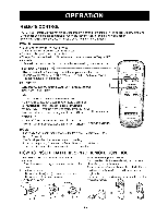
a screw ITEM G. See FIG. 12.
 |
View all Kenmore 75251 manuals
Add to My Manuals
Save this manual to your list of manuals |
Page 7 highlights
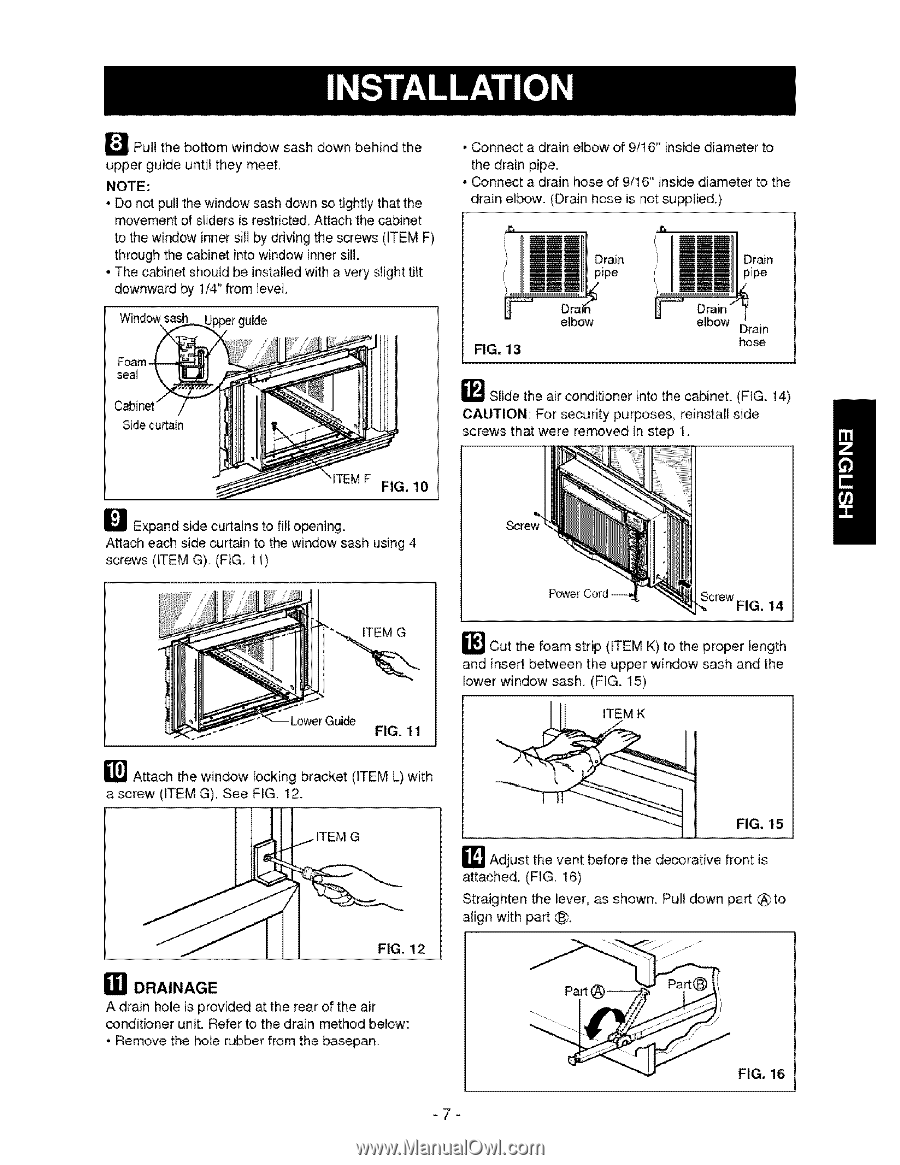
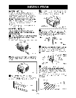
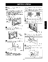
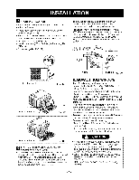
_PuH the bottom window sash down behind the upper guide until they meet, NOTE: • Do not pull the window sash down so tightly that the movement of sliders is restricted, Attach the cabinet to the window inner sill by drMng the screws 0TEM F) through the cabinet into window innersill. • The c_inet should be installed with a very slight ti_t downward by 1/4" from ]eve], Window sash • _nnect a drain elbow of 9/16" inside diameter to the drain pipe, • _nnect a drain hose of 9/16" inside diameter to the drain elbow. (Drain hose is not supplied.) Drain pipe FIG. 13 e_bow eMbow Drain hose _ Slide the air conditioner intothe cabinet. (FIG. 14) CAUTION: For security purposes, reinstall side screws that were removed in step I. _TEMF FIG, 10 _ Expand side curtains to fill opening. Attach each side curt:_n to the window sash using 4 screws (_TEM G) (F_G, 1i) ITEM G _Cut the, foam strip (_TEM K) to the proper _ength and inse_ between the upper window sash and the lower window sash.. (FIG. 15) _] Attach the window locking bracket (ITEM L) with a screw (ITEM G). See FIG. 12. ITEM G FIG. 12 a] DRAINAGE A drain hole is provide, at the rear of the air conditbner unit. Refer to the drain method below:: • Remove the hole wbber from the basepan. FiG. 15 _ Adjust the vent before the decorative front is attached, (FIG, 16) Straighten the lever, as shown. Pull down part @to align with part C_ !'%ili F_G, 16 -7=
-
 1
1 -
 2
2 -
 3
3 -
 4
4 -
 5
5 -
 6
6 -
 7
7 -
 8
8 -
 9
9 -
 10
10 -
 11
11 -
 12
12 -
13
-
14
-
15
-
16
-
17
-
18
-
19
-
20
-
21
-
22
-
23
-
24
-
25
-
26
-
27
-
28
-
29
-
30
-
31
-
32
 |
 |