Kenmore 7560 Installation Instructions - Page 5
Manual Flare, FlexibleFlareUnion Pressure - amps used
 |
View all Kenmore 7560 manuals
Add to My Manuals
Save this manual to your list of manuals |
Page 5 highlights
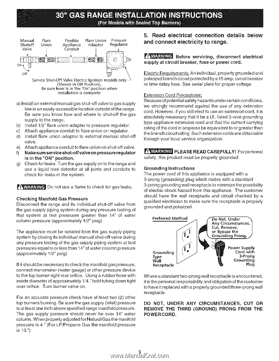
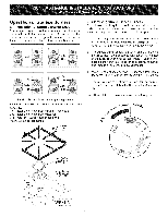
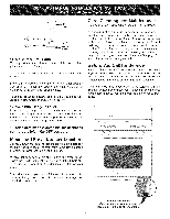
Manual Flare Shutoff Valve Union / Flexible FlareUnion Pressure Appliance Conduit Adaptor / Regulator off Service Shut=Off Valve Electric Ignition models only _ (Shown in ON Position). Be sure lever is in the "On" position when installation is complete a) Install an external manual gas shut-off valve to gas supply line in an easily-accessible location outside of the range. Be sure you know how and where to shut-off the gas supply to the range. b) Install 1/2" flare union adapterto pressure regulator. c) Attach appliance conduit to flare union on regulator. d) Install flare union adapter to external manual shut-off valve. e) Attach appliance conduit to flare union on shut-off valve. f) Make sure service shut-off valve on pressure regulator is in the "ON" position. g) Check for leaks. Turnthe gas supply on to the rangeand use a liquid leak detector at all joints and conduits to check for leaks in the system. Do not use a flame to check for gas leaks. Checking Manifold Gas Pressure Disconnect the range and its individual shut-off valve from the gas supply piping system during any pressure testing of that system at test pressures greater than 14" of water column pressure (approximately 1/2" psig). The appliance must be isolated from the gas supply piping system by closing its individual manual shut-off valve during any pressure testing of the gas supply piping system at test pressures equal to or less than 14" of water column pressure (approximately 1/2" psig). If it should be necessary to check the manifold gas pressure, connect manometer (water gauge) or other pressure device to the top burner right rear orifice. Using a rubber hose with inside diameter of approximately 1/4," hold tubing down tight over orifice. Turn burner valve on. For an accurate pressure check have at least two (2) other top burners burning. Be sure the gas supply (inlet) pressure is at least one inch above specified range manifold pressure. The gas supply pressure should never be over 14" water column. When properly adjusted for Natural Gas the manifold pressure is 4." (For LP/Propane Gas the manifold pressure is 10.") 5. Read electrical connection details below and connect electricity to range. Before servicing, disconnect electrical supply at circuit breaker, fuse or power cord. Electric Requirements: An individual, properly grounded and polarized branch circuit protected by a 15 amp. circuit breaker or time delay fuse. See serial plate for proper voltage. Extension Cord Precautions: Because of potential safety hazards under certain conditions, we strongly recommend against the use of any extension cord. However, if you still elect to use an extension cord, it is absolutely necessary that it be a UL listed 3-wire grounding type appliance extension cord and that the current carrying rating of the cord in amperes be equivalent to or greater than the branch circuit rating. Such extension cords are obtainable through your local service organization. PLEASE READ CAREFULLY! Forpersonal safety, this product must be properly grounded. Grounding Instructions The power cord of this appliance is equipped with a 3-prong (grounding) plug which mates with a standard 3-prong grounding wall receptacle to minimize the possibility of electric shock hazard from this appliance. The customer should have the wall receptacle and circuit checked by a qualified electrician to make sure the receptacle is properly grounded and polarized. Preferred Not, Under "_ Any Circumstances, I Cut, Remove, | or Bypass the J Grounding Prong._/ Grounding Type Wall Receptacle Power Supply Cord with 3-Prong Grounding Plug Where a standard two-prong wall receptacle is encountered, it is the personal responsibility and obligation of the customer to have it replaced with a properly grounded three-prong wall receptacle. DO NOT, UNDER ANY CIRCUMSTANCES, CUT OR REMOVE THE THIRD (GROUND) PRONG FROM THE POWER CORD.
-
 1
1 -
 2
2 -
 3
3 -
 4
4 -
 5
5 -
 6
6 -
 7
7 -
 8
8
 |
 |