Kenmore 7560 Installation Instructions - Page 6
Operation, of Surface, Burners - parts
 |
View all Kenmore 7560 manuals
Add to My Manuals
Save this manual to your list of manuals |
Page 6 highlights
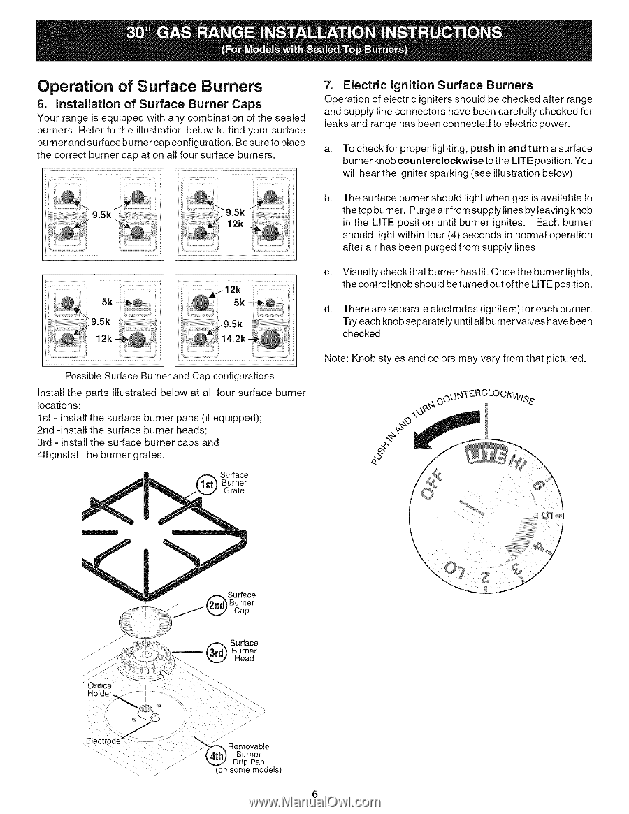
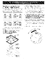
Operation of Surface Burners 6. Installation of Surface Burner Caps Your range is equipped with any combination of the sealed burners. Refer to the illustration below to find your surface burner and surface burner cap configuration. Be sureto place the correct burner cap at on all four surface burners. .... _ii ii i_...... _ii 7. Electric Ignition Surface Burners Operation of electric igniters should be checked after range and supply line connectors have been carefully checked for leaks and range has been connected to electric power. a. To check for proper lighting, push in and turn a surface burner knob counterclockwise to the UTE position. You will hear the igniter sparking (see illustration below). b, The surface burner should light when gas is available to thetop burner. Purge airfrom supply lines by leaving knob in the LITE position until burner ignites. Each burner should light within four (4) seconds in normal operation after air has been purged from supply lines. c. Visually check that burner has lit. Once the burner lights, the control knob should be turned out of the LITE position. d. There are separate electrodes (igniters) for each burner. Try each knob separately until all burner valves have been checked. Possible Surface Burner and Cap configurations Install the parts illustrated below at all four surface burner locations: 1st - Install the surface burner pans (if equipped); 2nd -install the surface burner heads; 3rd - install the surface burner caps and 4th;install the burner grates. Surface Burner Grate Note: Knob styles and colors may vary from that pictured. J_ _ Orifice I Hole n%Ce Cap Surface (_rd_ Burner _ Head j- Removable Burner Drip Pan (on some models)
-
 1
1 -
 2
2 -
 3
3 -
 4
4 -
 5
5 -
 6
6 -
 7
7 -
 8
8
 |
 |