Kenmore 9746 Installation Instructions - Page 3
Range, Connection, Opening, Chart - reviews
 |
View all Kenmore 9746 manuals
Add to My Manuals
Save this manual to your list of manuals |
Page 3 highlights
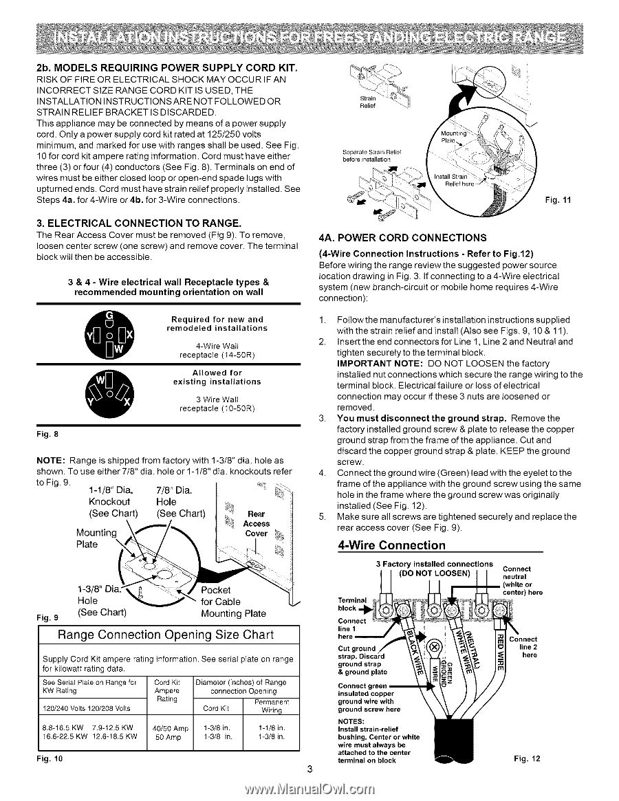
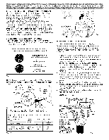
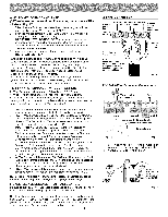
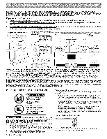
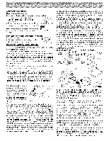
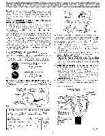
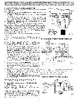
2b. MODELS REQUIRING POWER SUPPLY CORD KIT. RISK OF FIRE OR ELECTRICAL SHOCK MAY OCCUR IF AN INCORRECT SIZE RANGE CORD KIT IS USED, THE INSTALLATION INSTRUCTIONSARE NOT FOLLOWED OR STRAIN RELIEF BRACKET IS DISCARDED. This appliance may be connected by means of a power supply cord. Only a power supply cord kit rated at 125/250 volts minimum, and marked for use with ranges shall be used. See Fig. 10 for cord kit ampere rating information. Cord must have either three (3) or four (4) conductors (See Fig. 8). Terminals on end of wires must be either closed loop or open-end spade tugs with upturned ends. Cord must have strain relief properly installed. See Steps 4a. for 4-Wire or 4b. for 3-Wire connections. 3. ELECTRICAL CONNECTION TO RANGE. The Rear Access Cover must be removed (Fig 9). To remove, loosen center screw (one screw) and remove cover. The terminal block will then be accessible. 3 & 4 - Wire electrical wall Receptacle types & recommended mounting orientation on wall Required for new and remodeled installations 4-Wire Wall receptacle (14-50R) existing installations 3 Wire Wall O Allowed for receptacle (10-50R) Fig. 8 NOTE: Range is shipped from factory with 1-3/8" dia. hole as shown. To use either 7/8" dia. hole or 1-1/8" dia. knockouts refer to Fig. 9. 1-1/8" Dia. Knockout (See Chart) Mounting Plate 7/8" Dia. Hole (See Chart) " Rear Access Cover Fig. 9 1-3/8" Hole (See Chart) Range Connection Pocket for Cable Mounting Plate Opening Size Chart Supply Cord Kit ampere rating information. See serial plate on range for kilowatt rating data. See Serial Plate on Range for KW Rating 120/240 Volts 120/208 Volts Cord Kit Ampere Rating Diameter (inches) of Range connection Opening Permanent Cord Kit Wiring 8.8-16.5 KW 7.9-12.5 KW 16.6-22.5 KW 12.6-18.5 KW 40/50 Amp 50 Amp 1-3/8 in. 1-3/8 in. 1-1/8 in. I-3/8 in. Fig. 10 Separate Strain Relief before installation Fig. 11 4A. POWER CORD CONNECTIONS (4-Wire Connection Instructions - Refer to Fig.12) Before wiring the range review the suggested power source location drawing in Fig. 3. If connecting to a 4-Wire electrical system (new branch-circuit or mobile home requires 4-Wire connection): 1. Foltowthemanufacturer'sinstallationinstructionssupplied with the strain relief and install (Also see Figs. 9, 10 & 11 ). 2. Insert the end connectors for Line 1, Line 2 and Neutral and tighten securely to the terminal block. IMPORTANT NOTE: DO NOT LOOSEN the factory installed nut connections which secure the range wiring to the terminal block. Electrical failure or toss of electrical connection may occur if these 3 nuts are loosened or removed. 3. You must disconnect the ground strap. Remove the factory installed ground screw & plate to release the copper ground strap from the frame of the appliance. Cut and discard the copper ground strap & plate. KEEP the ground screw. 4. Connect the ground wire (Green) lead with the eyelet to the frame of the appliance with the ground screw using the same hole in the frame where the ground screw was originally installed (See Fig. 12). 5. Make sure all screws are tightened securely and replace the rear access cover (See Fig. 9). 4-Wire Connection 3 Factory installed connections (DO NOT LOOSEN) Terminal block Connect line 1 here Cut ground straF ground strap & ground plate Connect green insulated copper ground wire with ground screw here NOTES: Install strain-relief bushing. Center or white wire must always be attached to the center terminal on block Connect neutral or center) here Connect line 2 here Fig. 12
-
 1
1 -
 2
2 -
 3
3 -
 4
4 -
 5
5 -
 6
6 -
 7
7 -
 8
8
 |
 |