Kenmore 9746 Installation Instructions - Page 4
Connection - white electric range
 |
View all Kenmore 9746 manuals
Add to My Manuals
Save this manual to your list of manuals |
Page 4 highlights
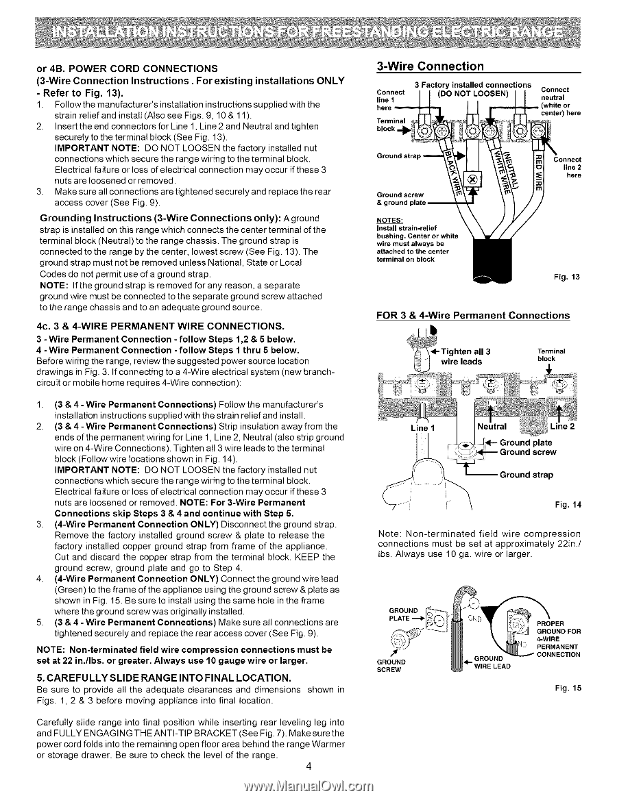
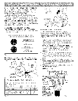
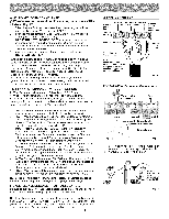
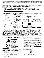
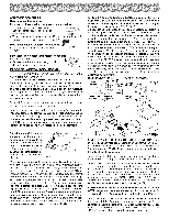
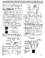
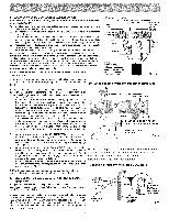
or 4B. POWER CORD CONNECTIONS (3-Wire Connection Instructions. For existing installations ONLY - Refer to Fig. 13). 1. Follow the manufacturer's installation instructions supplied with the strain relief and install (Also see Figs. 9, 10 & 11 ). 2. Insert the end connectors for Line 1, Line 2 and Neutral and tighten securely to the terminal block (See Fig. 13). IMPORTANT NOTE: DO NOT LOOSEN the factory installed nut connections which secure the range wiring to the terminal block. Electrical failure or loss of electrical connection may occur if these 3 nuts are loosened or removed. 3. Make sure all connections are tightened securely and replace the rear access cover (See Fig. 9). Grounding Instructions (3-Wire Connections only): A ground strap is installed on this range which connects the center terminal of the terminal block (Neutral) to the range chassis. The ground strap is connected to the range by the center, lowest screw (See Fig. 13). The ground strap must not be removed unless National, State or Local Codes do not permit use of a ground strap. NOTE: If the ground strap is removed for any reason, a separate ground wire must be connected to the separate ground screw attached to the range chassis and to an adequate ground source. 4c. 3 & 4-WIRE PERMANENT WIRE CONNECTIONS. 3 - Wire Permanent Connection - follow Steps 1,2 & 5 below. 4 -Wire Permanent Connection -follow Steps 1 thru 5 below. Before wiring the range, review the suggested power source location drawings in Fig. 3. If connecting to a 4-Wire electrical system (new branchcircuit or mobile home requires 4-Wire connection): 1. (3 & 4- Wire Permanent Connections) Follow the manufacturer's installation instructions supplied with the strain relief and install. 2. (3 & 4 - Wire Permanent Connections) Strip insulation away from the ends of the permanent wiring for Line 1, Line 2, Neutral (also strip ground wire on 4-Wire Connections). Tighten all 3 wire leads to the terminal block (Follow wire locations shown in Fig. 14). IMPORTANT NOTE: DO NOT LOOSEN the factory installed nut connections which secure the range wiring to the terminal block. Electrical failure or loss of electrical connection may occur if these 3 nuts are loosened or removed. NOTE: For 3-Wire Permanent Connections skip Steps 3 & 4 and continue with Step 5. 3. (4-Wire Permanent Connection ONLY) Disconnect the ground strap. Remove the factory installed ground screw & plate to release the factory installed copper ground strap from frame of the appliance. Cut and discard the copper strap from the terminal block. KEEP the ground screw, ground plate and go to Step 4. 4. (4-Wire Permanent Connection ONLY) Connect the ground wire lead (Green) to the frame of the appliance using the ground screw & plate as shown in Fig. 15. Be sure to install using the same hole in the frame where the ground screw was originally installed. 5. (3 & 4 - Wire Permanent Connections) Make sure all connections are tightened securely and replace the rear access cover (See Fig. 9). NOTE: Non-terminated field wire compression connections must be set at 22 in./Ibs, or greater. Always use 10 gauge wire or larger. 5. CAREFULLY SLIDE RANGE INTO FINAL LOCATION. Be sure to provide all the adequate clearances and dimensions Figs. 1, 2 & 3 before moving appliance into final location. shown in Carefully slide range into final position while inserting rear leveling leg into and FULLY ENGAGING THE ANTI-TIP BRACKET (See Fig. 7). Make sure the power cord folds into the remaining open floor area behind the range Warmer or storage drawer. Be sure to check the level of the range. 4 3-Wire Connection Connect line 1 here Terminal block 3 Factory installed connections (DO NOT LOOSEN) Connect neutral (white or center) here Ground screw & ground I: NOTES: Install strain-relief bushing. Center or white wire must always be attached to the center terminal on block Connect line 2 here Fig. 13 FOR 3 & 4-Wire Permanent Connections • Tighten all 3 wire leads Terminal block Line 1 Line 2 Ground plate Ground screw Ground strap Fig. 14 Note: Non-terminated field wire compression connections must be set at approximately 22in./ lbs. Always use 10 ga. wire or larger. GROUND PLATE ""_" GROUND SCREW PROPER GROUND FOR 4-WIRE NO PERMANENT GROUND CONNECTION RE LEAD Fig. 15
-
 1
1 -
 2
2 -
 3
3 -
 4
4 -
 5
5 -
 6
6 -
 7
7 -
 8
8
 |
 |