Kenwood D-S300 User Manual - Page 4
System connections
 |
View all Kenwood D-S300 manuals
Add to My Manuals
Save this manual to your list of manuals |
Page 4 highlights
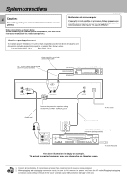
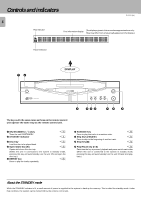
System connections 4 Caution: Do not plug in the power lead until all connections are completed. Make connections as shown below. When connecting the related system components, refer also to the instruction manuals of the related components. D-S300 (En) Malfunction of microcomputer If operation is not possible or erroneous display appears even though all connections have been made properly, reset the microcomputer referring to "In case of difficulty". ∞ Caution regarding placement To maintain proper ventilation, be sure to leave a space around the unit (from the largest outer dimensions including projections) equal to, or greater than, shown below. Left and right panels: 10 cm Rear panel: 10 cm Commercially-available optical fiber cable 75Ω coaxial cable with RCA PIN. (Commercially-available) (OPTICAL) DIGITAL INPUT (COAXIAL) Digital component (MD, DAT, etc.) L R LINE OUTPUT TEXT OPTICAL COAXIAL DIGITAL OUTPUT AC 110120V AC 220240V SISTEM CONTROL Remove the protection cap when using the DIGITAL OUTPUT (OPTICAL) jack. To AC outlet Audio cord CD L R SYSTEM CONTROL System control cord AV CONTROL CENTER (sold separately) or receiver (sold separately) AV CONTROL CERTER To wall AC outlet The above illustration is simply an example. The actual connected equipment may vary depending on the sales region. Notes 1. Connect all cords firmly. If connections are loose there could be loss of sound or noise produced. 2. When plugging and unplugging connection cords, be sure to first remove the power cord from the AC outlet. Plugging/unplugging connection cords without removal of the power cord can cause malfunctions or damage to the unit.
-
 1
1 -
 2
2 -
 3
3 -
 4
4 -
 5
5 -
 6
6 -
 7
7 -
 8
8 -
 9
9 -
 10
10 -
11
-
12
-
13
-
14
-
15
-
16
-
17
-
18
-
19
-
20
-
21
-
22
-
23
-
24
-
25
-
26
-
27
-
28
 |
 |
