Kenwood DDX1035 Operation Manual 1 - Page 36
Connecting Wires to Terminals
 |
View all Kenwood DDX1035 manuals
Add to My Manuals
Save this manual to your list of manuals |
Page 36 highlights
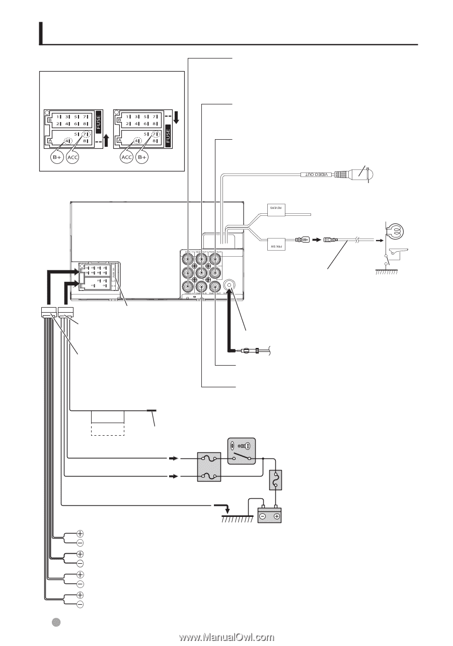
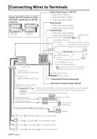
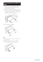
Connecting Wires to Terminals Change the FUSE location to switch ACC and B+ pin location on the ISO connector. Audio Video input 1 (AV IN1) • Video input (Yellow) • Audio left input (White) • Audio right input (Red) Rear Preout • Audio left output (White) • Audio right output (Red) Front Preout • Audio left output (White) • Audio right output (Red) Video Output Purple/White (Reverse sensor wire) Connect to vehicle's reverse lamp harness when using the optional rear view camera. FUSE ( 15A ) Accessory 1 (DDX1035/DDX1035M only) Accessory 2 (DDX1035/DDX1035M only) Light Green (Parking sensor wire) Extension cable (Accessory 3) For best safety, be sure to connect the parking sensor. ⁄ Connect to the vehicle's parking brake detection switch harness. FM/AM antenna input Antenna Cord Subwoofer Preout (monaural) Blue/White (Power control/ Rear View Camera Input (Yellow) Antenna control wire) To the power control terminal when using the optional power amplifier, P.CONT. or to the antenna control terminal in the vehicle. (Max. 350mA, 12V) ANT.CONT. If no connections are made, do not remove the cap. Red (Ignition wire) ACC Yellow (Battery wire) B+ Black (Ground wire) · (To car chassis) Ignition key switch Car fuse box (Main fuse) Battery White ª / White/black · : To front speaker (left) Gray ª / Gray/black · : To front speaker (right) Green ª / Green/black · : To rear speaker (left) Purple ª / Purple/black · : To rear speaker (right) 36 English
-
 1
1 -
2
-
3
-
4
-
5
-
6
-
7
-
8
-
9
-
10
-
11
-
12
-
13
-
14
-
15
-
16
-
17
-
18
-
19
-
20
-
21
-
22
-
23
-
24
-
25
-
26
-
27
-
28
-
29
-
30
-
 31
31 -
 32
32 -
 33
33 -
 34
34 -
 35
35 -
 36
36 -
 37
37 -
 38
38 -
 39
39 -
 40
40 -
 41
41 -
42
-
43
-
44
-
45
-
46
-
47
-
48
-
49
-
50
-
51
-
52
-
53
-
54
-
55
-
56
-
57
-
58
-
59
-
60
-
61
-
62
-
63
-
64
-
65
-
66
-
67
-
68
-
69
-
70
-
71
-
72
-
73
-
74
-
75
-
76
-
77
-
78
-
79
-
80
-
81
-
82
-
83
-
84
 |
 |