KitchenAid KEBS278SSS Technical Guide - Page 15
Installation Information - cutout
 |
UPC - 883049034867
View all KitchenAid KEBS278SSS manuals
Add to My Manuals
Save this manual to your list of manuals |
Page 15 highlights
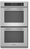
INSTALLATION INFORMATION INSTALLATION REQUIREMENTS TOOLS AND PARTS Gather the required tools and parts before starting installation. Read and follow the instructions provided with any tools listed here. Tools needed • Phillips screwdriver • Measuring tape • Hand or electric drill (for wall cabinet instal- lations) • 1˝ (25 mm) drill bit (for wall cabinet instal- lations) • Level Parts needed • UL listed or CSA approved conduit connector • UL listed wire connectors Parts supplied • # 8-14 x 1˝ screws - single oven (2), double oven (4) • Bottom vent (supplied on some models) • Two # 8-18 x 3/8˝ screws - bottom vent (sup- plied on some models) Check local codes. Check existing electrical supply. See "Electrical Requirements," page 2-2. It is recommended that all electrical connections be made by a licensed, qualified electrical installer. • Recessed installation area must provide complete enclosure around the recessed portion of the oven. • Grounded electrical supply is required. See "Electrical Requirements," page 2-2. • Electrical supply junction box should be located 3˝ (7.6 cm) maximum below the support surface when the oven is installed in a wall cabinet. A 1˝ (2.5 cm) minimum diameter hole should have been drilled in the right rear or left rear corner of the support surface to pass the appliance cable through to the junction box. • Oven support surface must be solid, level and flush with bottom of cabinet cutout. Floor must be able to support a total weight (double built-in oven) of 287 lbs (108 kg). Product Dimensions 27˝ (68.6 cm) and 30˝ (76.2 cm) Ovens A B E LOCATION REQUIREMENTS Make sure you have everything needed for correct installation. It is the responsibility of the installer to comply with the installation clearances specified in these instructions. IMPORTANT: Observe all governing codes and ordinances. • Cabinet opening dimensions that are shown must be used. Given dimensions provide minimum clearance with oven. D C 27" (68.6 cm) models A. 25 5/16" (64.3 cm) max. recessed width B.50 3/4 " (128.9 cm) max. overall height C. 26 3/4 " (67.9 cm) overall width D. 23" (58.4 cm) max. recessed depth E. 49 9/16 " (125.9 cm) recessed height 30" (76.2 cm) models A. 28 5/16 " (71.9 cm) max. recessed width B. 50 3/4 " (128.9 cm) max. overall height C. 29 3/4 " (75.6 cm) overall width D. 23" (58.4 cm) max. recessed depth E. 49 9/16 " (125.9 cm) recessed height 3 2-1
-
 1
1 -
2
-
3
-
4
-
5
-
6
-
7
-
8
-
9
-
 10
10 -
 11
11 -
 12
12 -
 13
13 -
 14
14 -
 15
15 -
 16
16 -
 17
17 -
 18
18 -
 19
19 -
 20
20 -
21
-
22
-
23
-
24
-
25
-
26
-
27
-
28
-
29
-
30
-
31
-
32
-
33
-
34
-
35
-
36
-
37
-
38
-
39
-
40
-
41
-
42
-
43
-
44
-
45
-
46
-
47
-
48
-
49
-
50
-
51
-
52
-
53
-
54
-
55
-
56
-
57
-
58
-
59
-
60
-
61
-
62
-
63
-
64
-
65
-
66
-
67
-
68
-
69
-
70
-
71
-
72
-
73
-
74
-
75
-
76
-
77
-
78
-
79
-
80
-
81
-
82
-
83
-
84
-
85
-
86
-
87
-
88
-
89
-
90
 |
 |
