KitchenAid KVIB606DBS Installation Guide - Page 4
Installation Requirements
 |
View all KitchenAid KVIB606DBS manuals
Add to My Manuals
Save this manual to your list of manuals |
Page 4 highlights
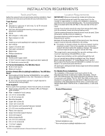
INSTALLATION REQUIREMENTS Tools and Parts Gather the required tools and parts before starting installation. Read and follow the instructions provided with any tools listed here. Tools Needed ■ Level ■ Drill with 1¼" (3.0 cm 9.5 mm 2.75 mm) and ¹⁄₈" (3.0 mm) drill bits ■ Pilot hole drill bits (determined by chimney support attachment method) ■ Pencil ■ Wire stripper or utility knife ■ Tape measure or ruler ■ Pliers ■ Caulking gun and weatherproof caulking compound ■ Vent clamps ■ Jigsaw or keyhole saw ■ Flat-blade screwdriver ■ Metal snips ■ Phillips screwdriver Parts Needed ■ Home power supply cable ■ ½" (12.7 mm) UL listed or CSA approved strain reliefs (2) ■ UL listed wire connectors (3) For Vented Installations, You Will Also Need: ■ W all or roof cap (1) ■ Metal vent system For Non-Vented (Recirculating) Installations, You Will Also Need: ■ Recirculating Kit Part Number W10692909 for non-vented (recirculating) installations only. See "Assistance or Service" section to order. ■ 6" (15.2 cm) round metal vent duct. Length required is determined by ceiling height. Parts Supplied Remove parts from packages. Check that all parts are included. ■ Hood canopy assembly with ventilator, LED and Halogen lights installed. ■ Filter-installed in hood canopy ■ 4.2 x 8 mm screws (60) ■ 5 x 45 mm screws (4) ■ Mounting template ■ Upper vent covers (2) ■ Lower vent covers (2) ■ Vent transition with backdraft damper installed ■ 3.5 x 9.5 mm mounting screws (2) ■ Plastic vent clips (4) ■ Upper horizontal support bracket ■ Horizontal support ■ Vertical supports (8) ■ 3.5 x 6.5 mm screws (4) ■ 2.9 x 3 mm screws (2) ■ T-10 Torx®† adapter ■ T20 Torx adapter †®TORX is a registered trademark of Acument Intellectual Properties, LLC. 4 Location Requirements IMPORTANT: Observe all governing codes and ordinances. Have a qualified technician install the range hood. It is the installer's responsibility to comply with installation clearances specified on the model/serial/rating plate. The model/serial/rating plate is located behind the left filter on the rear wall of the vent hood. Canopy hood location should be away from strong draft areas, such as windows, doors and strong heating vents. Cabinet opening dimensions that are shown must be used. Given dimensions provide minimum clearance. Grounded electrical outlet is required. See "Electrical Requirements" section. Because of the size and weight of this island hood, the chimney support must be securely attached to the ceiling. ■ For plaster or drywall ceilings, the chimney support must be attached to joists. If this is not possible, you must build a support structure behind the plaster or drywall. The support structure must be able to support 100 lbs (45.4 kg). This range hood is recommended for use with cooktops with a maximum total rating of 65,000 BTUs or less. The range hood is factory-set for venting through the roof. For non-vented (recirculating) installation see "Non-Vented (Recirculating) Installation" in "Install Range Hood" section. Recirculation Kit Part Number W10692909 is available from your dealer or an authorized parts distributor. All openings in ceiling and wall where range hood will be installed must be sealed. For Mobile Home Installations The installation of this range hood must conform to the Manufactured Home Construction Safety Standards, Title 24 CFR, Part 328 (formerly the Federal Standard for Mobile Home Construction and Safety, Title 24, HUD, Part 280) or when such standard is not applicable, the standard for Manufactured Home Installation 1982 (Manufactured Home Sites, Communities and Setups) ANSI A225.1/NFPA 501A, or latest edition, or with local codes. Product Dimensions 36" (91.2 cm) 42" (106.4 cm) 27" (68.6 cm) *Vented installations only **Non-vented (recirculating) installations only
-
 1
1 -
 2
2 -
 3
3 -
 4
4 -
 5
5 -
 6
6 -
 7
7 -
 8
8 -
 9
9 -
 10
10 -
11
-
12
-
13
-
14
-
15
-
16
-
17
-
18
-
19
-
20
-
21
-
22
-
23
-
24
-
25
-
26
-
27
-
28
-
29
-
30
-
31
-
32
 |
 |
