LG 42LK451C Owners Manual - Page 13
Cross - tv model
 |
View all LG 42LK451C manuals
Add to My Manuals
Save this manual to your list of manuals |
Page 13 highlights
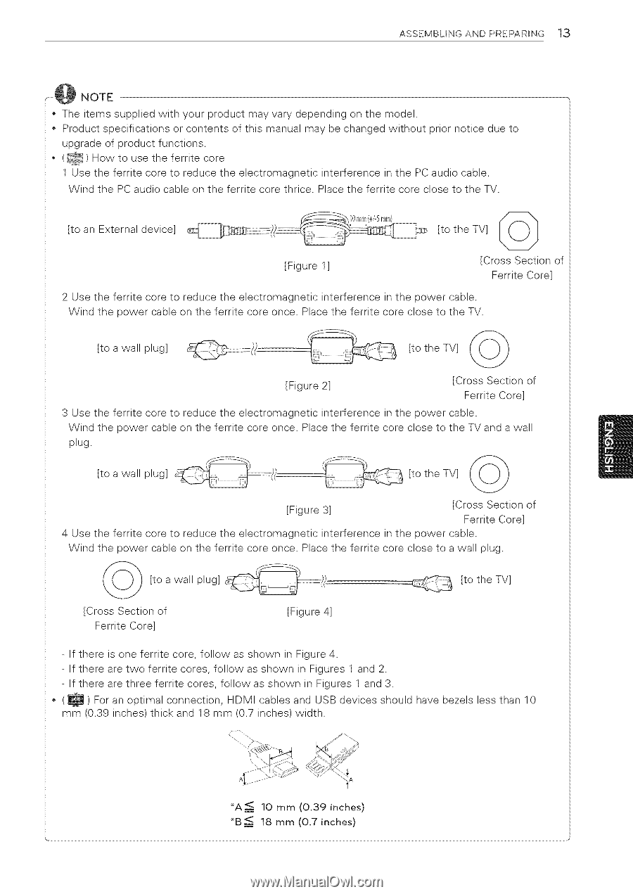
ASSEMBLING AND PREPARING 13 NOTE • The items supplied with your product may vary depending on the model. • Product specifications or contents of this manual may be changed without prior notice due to upgrade of product functions. • (_) How to use the ferrite core 1 Use the ferrite core to reduce the electromagnetic interference in the PC audio cable. Wind the PC audio cable on the ferrite core thrice. Place the ferrite core close to the TV. [to an External device] [to theTV] ((j)_ [Figure 1] [Cross Section of Ferrite Core] 2 Use the ferrite core to reduce the electromagnetic interference in the power cable. Wind the power cable on the ferrite core once. Place the ferrite core close to the TV. [to a wall plug] [to the TV] _',,(_9 [Figure 2] [Cross Section of Ferrite Core] 3 Use the ferrite core to reduce the electromagnetic interference in the power cable. Wind the power cable on the ferrite core once. Place the ferrite core close to the TV and a wall plug. [to a wall plug] [to the TV] _,_)/,) [Figure 3] [Cross Section of Ferrite Core] 4 Use the ferrite core to reduce the electromagnetic interference in the power cable. Wind the power cable on the ferrite core once. Place the ferrite core close to a wall plug. a plug] (_ [to wall [Cross Section of Ferrite Core] [Figure 4] _ [to theTV] - If there is one ferrite core, follow as shown in Figure 4. - If there are two ferrite cores, follow as shown in Figures 1 and 2. - If there are three ferrite cores, follow as shown in Figures 1 and 3. • (_) For an optimal connection, HDMI cables and USB devices should have bezels less than 10 mm (0.39 inches)thick and 18 mm (0.7 inches)width. _A_ *B
-
 1
1 -
2
-
3
-
4
-
5
-
6
-
7
-
 8
8 -
 9
9 -
 10
10 -
 11
11 -
 12
12 -
 13
13 -
 14
14 -
 15
15 -
 16
16 -
 17
17 -
 18
18 -
19
-
20
-
21
-
22
-
23
-
24
-
25
-
26
-
27
-
28
-
29
-
30
-
31
-
32
-
33
-
34
-
35
-
36
-
37
-
38
-
39
-
40
-
41
-
42
-
43
-
44
-
45
-
46
-
47
-
48
-
49
-
50
-
51
-
52
-
53
-
54
-
55
-
56
-
57
-
58
-
59
-
60
-
61
-
62
-
63
-
64
-
65
-
66
-
67
-
68
-
69
-
70
-
71
-
72
-
73
-
74
-
75
-
76
-
77
-
78
-
79
-
80
-
81
-
82
-
83
-
84
-
85
-
86
-
87
-
88
-
89
-
90
-
91
-
92
-
93
-
94
-
95
-
96
-
97
-
98
-
99
-
100
-
101
-
102
-
103
-
104
-
105
-
106
-
107
-
108
-
109
-
110
-
111
-
112
-
113
-
114
-
115
-
116
-
117
-
118
-
119
-
120
-
121
-
122
-
123
-
124
-
125
-
126
-
127
-
128
 |
 |