LG 50PC1DR Owners Manual - Page 45
CONTROL Board
 |
View all LG 50PC1DR manuals
Add to My Manuals
Save this manual to your list of manuals |
Page 45 highlights
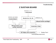
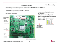
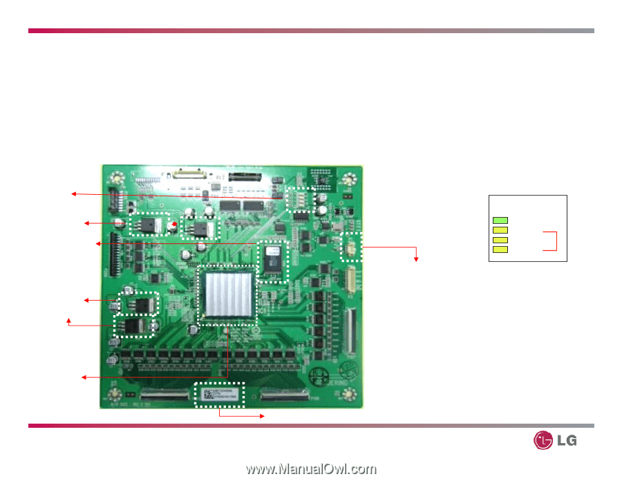
CONTROL Board Troubleshooting ◆. In charge of all signal process and creating ON/OFF order of all FET on DRIVER B/D by receiving 8 bit R, G, B input. ◆. Power : 3.3V/5V Temperature diode Voltage Regulator Flash ROM Voltage Regulator Temperature display diode can be checked. Left picture shows 7 periods which means normal temperature Green = OFF Yellow = ON Weight D15 - 8 D16 - 4 D17 - 2 D18 - 1 TEST Pattern AUTOGEN P1 Connector MCM (Micro Control Module) Plasma Display Panel Troubleshooting - 2007 LG Part Number Label 45
-
 1
1 -
2
-
3
-
4
-
5
-
6
-
7
-
8
-
9
-
10
-
11
-
12
-
13
-
14
-
15
-
16
-
17
-
18
-
19
-
20
-
21
-
22
-
23
-
24
-
25
-
26
-
27
-
28
-
29
-
30
-
31
-
32
-
33
-
34
-
35
-
36
-
37
-
38
-
39
-
 40
40 -
 41
41 -
 42
42 -
 43
43 -
 44
44 -
 45
45 -
 46
46 -
 47
47 -
 48
48 -
 49
49 -
 50
50 -
51
-
52
-
53
-
54
-
55
-
56
-
57
-
58
-
59
-
60
-
61
-
62
-
63
-
64
-
65
-
66
-
67
-
68
-
69
-
70
-
71
-
72
-
73
-
74
-
75
-
76
-
77
-
78
-
79
-
80
-
81
-
82
-
83
-
84
-
85
-
86
-
87
-
88
-
89
-
90
-
91
-
92
-
93
-
94
-
95
-
96
-
97
-
98
-
99
-
100
 |
 |
45
Plasma Display Panel Troubleshooting - 2007
Flash ROM
Voltage
Regulator
Temperature
diode
◆
.
In charge of all signal process and creating ON/OFF order of all FET on
DRIVER B/D by receiving 8 bit R, G, B input.
◆
. Power
:
3.3V/5V
Temperature display diode can
be checked.
Left picture shows 7 periods
which means normal temperature
Green = OFF
Yellow = ON
D15 - 8
Weight
D16 - 4
D17 - 2
D18 - 1
Voltage
Regulator
MCM
(Micro
Control
Module)
Troubleshooting
CONTROL Board
TEST Pattern
AUTOGEN
P1 Connector
LG Part Number Label