LG 50PC1DR Owners Manual - Page 7
Troubleshooting - won t turn on
 |
View all LG 50PC1DR manuals
Add to My Manuals
Save this manual to your list of manuals |
Page 7 highlights
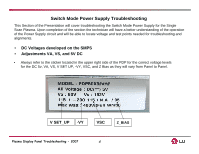
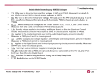
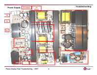
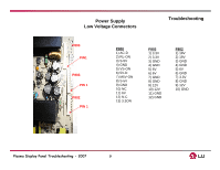
Switch Mode Power Supply (SMPS) Voltages Troubleshooting • VS 196v used to drive the Horizontal Grid Voltage, Y SUS, and Z SUS. Measured from pins 8, 9, and 10 of connector P805 to chassis ground. Adjusted at VR951 • VA 60v used to drive the Vertical Grid Voltage, X Boards and in the IPM Circuits to develop Y and Z Drive waveforms. Measured from pins 1 and 2 of connector P805 to chassis ground. Adjusted at VR901 • 5v.DC Used to develop bias voltages for the circuits on the Y SUS, Z SUS, X, and Control Boards. Measured from pins 1 and 2 of connector P804 to chassis ground. • 3.3v. Standby voltage applied to the Analog, and Digital Boards to Bias the Signal and Control circuits. Measured at connector P803 at pins 1 and 2. to chassis ground. Adjusted at VR221. • 19v Applied to the Analog Board and used for the Audio Output Supply, present in standby. Measured at P802 pins 1 and 2 to chassis ground. • 12v Used for supplying low voltage regulators on the Digital and Analog Boards, present in standby. Measured at P803 pins 9 and 10 to chassis ground. • 6v Applied to the Digital Board used for the signal processing circuits present in standby. Measured at P803 pins 5 and 6 to chassis ground. • S 5v Standby 5 volts at P800 pin 3 applied to the Digital Board. • VS- ON Switched 5 volts at P800 pin 5 present after power up to switch on the VA, VS, and 5V on the Power Board from the Digital Board. • 5v-D Switched 5v used to bring the Power Supply out of Deep Sleep Mode. • 5V-M Needed to turn on the 5V-DC Supply. Plasma Display Panel Troubleshooting - 2007 7
-
 1
1 -
 2
2 -
 3
3 -
 4
4 -
 5
5 -
 6
6 -
 7
7 -
 8
8 -
 9
9 -
 10
10 -
 11
11 -
 12
12 -
13
-
14
-
15
-
16
-
17
-
18
-
19
-
20
-
21
-
22
-
23
-
24
-
25
-
26
-
27
-
28
-
29
-
30
-
31
-
32
-
33
-
34
-
35
-
36
-
37
-
38
-
39
-
40
-
41
-
42
-
43
-
44
-
45
-
46
-
47
-
48
-
49
-
50
-
51
-
52
-
53
-
54
-
55
-
56
-
57
-
58
-
59
-
60
-
61
-
62
-
63
-
64
-
65
-
66
-
67
-
68
-
69
-
70
-
71
-
72
-
73
-
74
-
75
-
76
-
77
-
78
-
79
-
80
-
81
-
82
-
83
-
84
-
85
-
86
-
87
-
88
-
89
-
90
-
91
-
92
-
93
-
94
-
95
-
96
-
97
-
98
-
99
-
100
 |
 |