LG 50PX5D Owners Manual - Page 9
Connection Options - service manual
 |
View all LG 50PX5D manuals
Add to My Manuals
Save this manual to your list of manuals |
Page 9 highlights
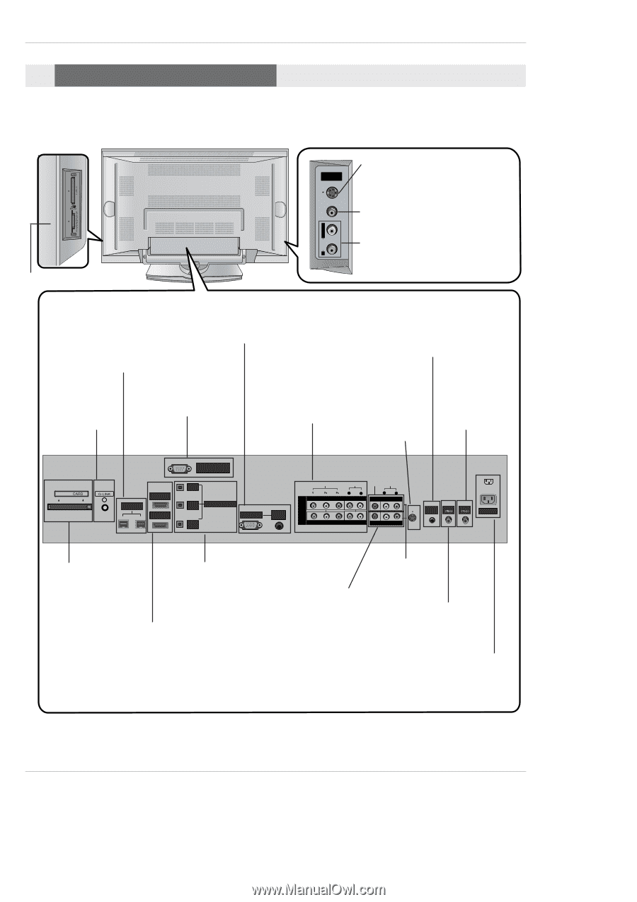
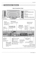
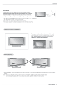
Connection Options Introduction Back Connection Panel Memory Card Slots R AUDIO L / MONO VIDEO S-VIDEO Input FRONT A/V INPUT S-VIDEO A connection is available to provide better picture quality than the video input. VIDEO Input Connects the video signal from a video device. AUDIO Input Connections are available for listening stereo sound from an external device. RGB/AUDIO INPUT IEEE1394 Connect the monitor output Connect a DVHS, a from a PC to the appropriate MicroMV Camcorder, or input port. a set-top box to IEEE1394 Connector. DVD/DTV Input G-LINKTM Connect an IR controller to this RS-232C INPUT (CONTROL/SERVICE) PORT Connect to the RS-232C port on a PC. (Component 1-2) Connect a component video/audio device to these jacks. jack. Remote Control Port Connect your wired remote control here. S-Video Input Connect SVideo out from an S-VIDEO device to the SVIDEO input. Antenna Input Connect over-theair signals to this jack. Cable IEEE-1394 HDMI 2 HDMI1/DVI RS-232C INPUT (CONTROL/SERVICE) OUTPUT COMPONENT2 INPUT DVI INPUT DIGITAL AUDIO (OPTICAL) RGB INPUT AUDIO INPUT DVD /DTV INPUT VIDEO AUDIO L R COMPONENT INPUT 2 VIDEO AUDIO L R MONITOR OUTPUT COMPONENT INPUT 1 (MONO) A/V INPUT REMOTE CONTROL CABLE ANTENNA S-VIDEO AC INPUT CableCARD™ Digital Audio (DVI: Digital Used for Visual CableCARD™ Interface/Component2) received from Cable Input/ Service Provider. Digital Audio Output Connect digital audio from HDMI1/DVI, HDMI 2 various types of equipment. Connect a HDMI sig- Note: In standby mode, nal to HDMI1/DVI or these ports will not work. HDMI2. Or connect a DVI(Video) signal to HDMI1/DVI. Monitor Output Connect a second Audio/Video Input TV or Monitor. Connect audio/video output from an CABLE Input external device to Connect cable signals to this these jacks. jack, either directly or through a cable box. Power Cord Socket This TV operates on an AC power. The voltage is indicated on the Specifications page. Never attempt to operate the TV on DC power. Owner's Manual 9
-
 1
1 -
2
-
3
-
 4
4 -
 5
5 -
 6
6 -
 7
7 -
 8
8 -
 9
9 -
 10
10 -
 11
11 -
 12
12 -
 13
13 -
 14
14 -
15
-
16
-
17
-
18
-
19
-
20
-
21
-
22
-
23
-
24
-
25
-
26
-
27
-
28
-
29
-
30
-
31
-
32
-
33
-
34
-
35
-
36
-
37
-
38
-
39
-
40
-
41
-
42
-
43
-
44
-
45
-
46
-
47
-
48
-
49
-
50
-
51
-
52
-
53
-
54
-
55
-
56
-
57
-
58
-
59
-
60
-
61
-
62
-
63
-
64
-
65
-
66
-
67
-
68
-
69
-
70
-
71
-
72
-
73
-
74
-
75
-
76
-
77
-
78
-
79
-
80
-
81
-
82
-
83
-
84
-
85
-
86
-
87
-
88
-
89
-
90
-
91
-
92
-
93
-
94
-
95
-
96
-
97
-
98
-
99
-
100
-
101
-
102
-
103
-
104
-
105
-
106
 |
 |