LG DLG2524W Owners Manual - Page 10
For LP Liquefied - review
 |
View all LG DLG2524W manuals
Add to My Manuals
Save this manual to your list of manuals |
Page 10 highlights
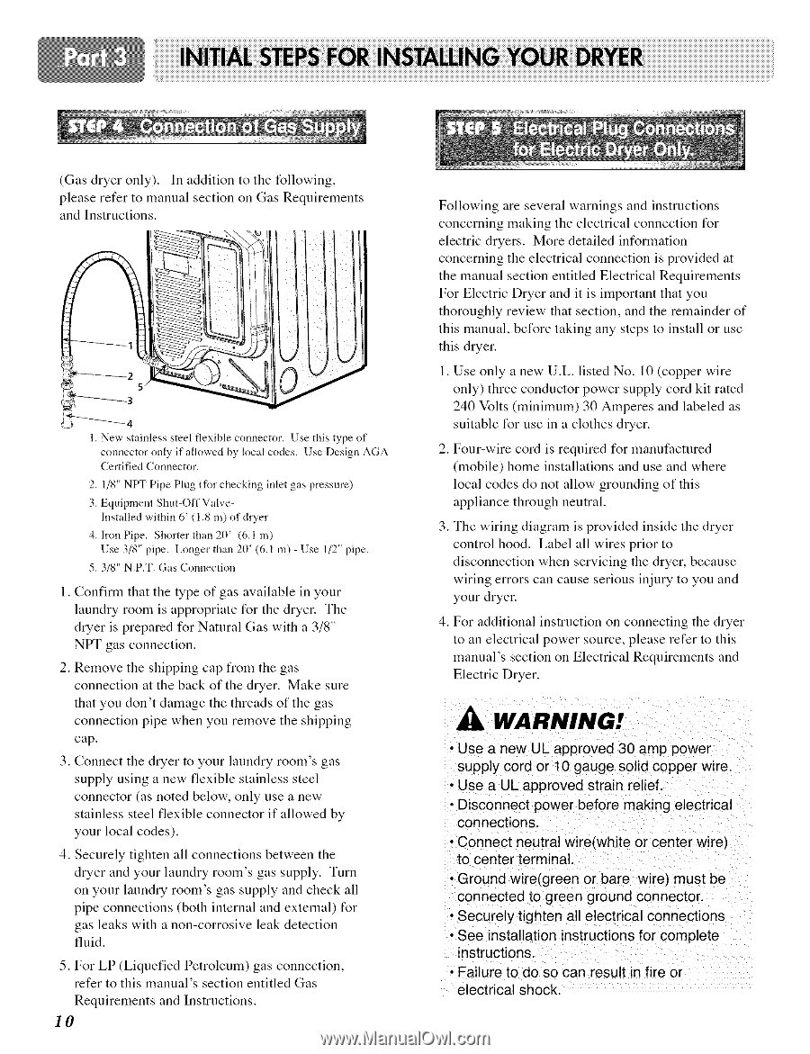
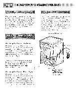
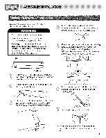
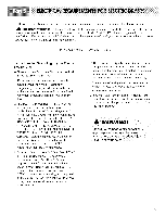
(Gas dryer only). In addition to the following, please refer to manual section on Gas Requirements and Instructions. _2 5 _-3 New stainless steel flexible connector. Use this type of connector only if allowed by local codes. Use Design AGA Certified Connector. 2. 1/8" NPT Pipe Plug (for checking inlet gas pressure) 3. Equipment Shut-Off ValveInstalled within 6' ( 1.8 m) of dryer 4. Iron Pipe. Shorter than 20' (6,1 m) Use 3/8" pipe. Longer than 20' (6.1 m) - Use 1/2" pipe. 5.3/8" N.P.T. Gas Conuection 1. Confirm that the type of gas available in your laundry room is appropriate for the dryer. The dryer is prepared for Natural Gas with a 3/8" NPT gas connection. 2. Remove the shipping cap from the gas connection at the back of the dryer. Make sure that you don't damage the threads of the gas connection pipe when you remove the shipping cap. 3. Connect the dryer to your laundry room's gas supply using a new flexible stainless steel connector (as noted below, only use a new stainless steel flexible connector if allowed by your local codes). 4. Securely tighten all connections between the dryer and your laundry room's gas supply. Turn on your laundry room's gas supply and check all pipe connections (both internal and external) for gas leaks with a non-corrosive leak detection fluid. 5. For LP (Liquefied Petroleum) gas connection, refer to this manual's section entitled Gas Requirements and Instructions. IO Following are several warnings and instructions concerning making the electrical connection for electric dryers. More detailed information concerning the electrical connection is provided at the manual section entitled Electrical Requirements For Electric Dryer and it is important that you thoroughly review that section, and the remainder of this manual, before taking any steps to install or use this dryer. 1. Use only a new U.L. listed No. 10 (copper wire only) three conductor power supply cord kit rated 240 Volts (minimum) 30 Amperes and labeled as suitable for use in a clothes dryer. 2. Four-wire cord is requited for manufactured (mobile) home installations and use and where local codes do not allow grounding of this appliance through neutral. 3. Thc wiring diagram is providcd insidc thc drycr control hood. Label all wires prior to disconnection when servicing the dryer, because wiring errors can cause serious injury to you and your dryer. 4. For additional instruction on connecting the dryer to an electrical power source, please refer to this manual's section on Electrical Requirements and Electric Dryer. WARNING! • Use a new UL approved 30 amp power supply cord or 10 gauge solid copper wire. • Use a UL approved strain relief. • Disconnect power before making electrical connections. • Connect neutral wire(white or center wire) to center terminal. • Ground wire(green or bare wire) must be connected to green ground connector. • Securely tighten all electrical connections • See installation instructions for complete instructions. • Failure to do so can result in fire or electrical shock.
-
 1
1 -
2
-
3
-
4
-
 5
5 -
 6
6 -
 7
7 -
 8
8 -
 9
9 -
 10
10 -
 11
11 -
 12
12 -
 13
13 -
 14
14 -
 15
15 -
16
-
17
-
18
-
19
-
20
-
21
-
22
-
23
-
24
-
25
-
26
-
27
-
28
-
29
-
30
-
31
-
32
 |
 |