LG LCU240CP Service Manual - Page 19
Wiring Diagrams
 |
View all LG LCU240CP manuals
Add to My Manuals
Save this manual to your list of manuals |
Page 19 highlights
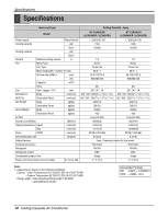
Wiring Diagrams 1. Indoor Unit LCN240CP/LC240CPI/LCN340CP/LC340CPI Wiring Diagrams Connector Number CN-POWER CN-MOTOR CN-DPUMP CN-DISP CN-FLOAT CN-REMO CN-CC CN-ROOM CN-PIPE1 CN-PIPE2 CN-GRILL CN-PTC CN-HVB Location AC power supply BLDC fan motor output Drain pump output Display Float switch input Remote control Dry-contact Room sensor In-pipe thermistor Out-pipe thermistor Elevation grille PTC Heater HVB Ass'y (Air cleaner) Service Manual 19
-
 1
1 -
2
-
3
-
4
-
5
-
6
-
7
-
8
-
9
-
10
-
11
-
12
-
13
-
 14
14 -
 15
15 -
 16
16 -
 17
17 -
 18
18 -
 19
19 -
 20
20 -
 21
21 -
 22
22 -
 23
23 -
 24
24 -
25
-
26
-
27
-
28
-
29
-
30
-
31
-
32
-
33
-
34
-
35
-
36
-
37
-
38
-
39
-
40
-
41
-
42
-
43
-
44
-
45
-
46
-
47
-
48
-
49
-
50
-
51
-
52
-
53
-
54
-
55
-
56
-
57
-
58
-
59
-
60
-
61
 |
 |

Service Manual
19
Wiring Diagrams
1. Indoor Unit
LCN240CP/LC240CPI/LCN340CP/LC340CPI
Wiring Diagrams
Connector Number
Location
CN-POWER
AC power supply
CN-MOTOR
BLDC fan motor output
CN-DPUMP
Drain pump output
CN-DISP
Display
CN-FLOAT
Float switch input
CN-REMO
Remote control
CN-CC
Dry-contact
CN-ROOM
Room sensor
CN-PIPE1
In-pipe thermistor
CN-PIPE2
Out-pipe thermistor
CN-GRILL
Elevation grille
CN-PTC
PTC Heater
CN-HVB
HVB Ass'y (Air cleaner)